For dual-slope PWM generation, the period (T) is controlled by TCAn.PER, while the values of TCAn.CMPm control the duty cycle of the WG output.
The figure below shows how, for dual-slope PWM, the counter counts repeatedly from BOTTOM to TOP and then from TOP to BOTTOM. The waveform generator output is set on BOTTOM, cleared on compare match when up-counting and set on compare match when down-counting.
CMPn = BOTTOM will produce a static low signal on WOn, while CMPn = TOP will produce a static high signal on WOn.
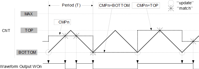
Using dual-slope PWM results in half the maximum operation frequency compared to single-slope PWM operation, due to twice the number of timer increments per period.
The period register (TCAn.PER) defines the PWM resolution. The minimum resolution is 2 bits (TCAn.PER = 0x0003), and the maximum resolution is 16 bits (TCAn.PER = MAX).
The following equation calculates the exact resolution in bits for dual-slope PWM (RPWM_DS):
The PWM frequency depends on the period setting (TCAn.PER), the peripheral clock frequency (fCLK_PER) and the prescaler divider used (CLKSEL in TCAn.CTRLA). It is calculated by the following equation:
N represents the prescaler divider used.