The pinout for the 6-pin PDI connector is shown in Figure 1.
Be sure to use the correct orientation of the 6-pin header when connecting the Atmel AVR ONE! to the target application PCB. The stand-off adapters (provided) can be used to connect the AVR ONE! probe to both 100-mil and 50-mil target application connectors.
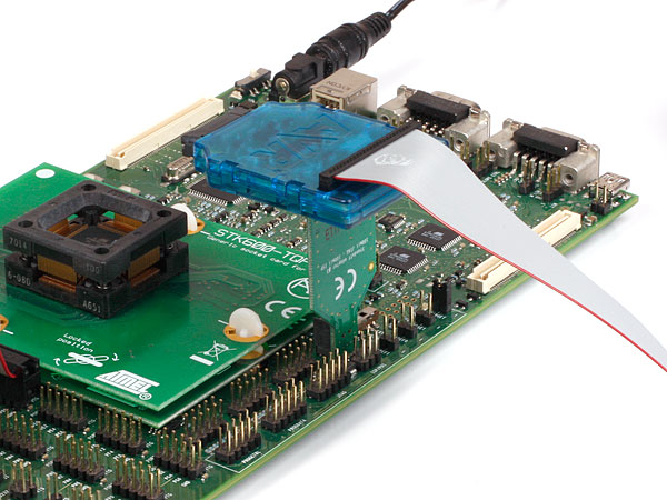
When connecting to a target that does not have the standard 6-pin header, you can use the squid cable between the AVR ONE! 10-pin JTAG connector on the probe and the target board.4 connections are required, and the table below describes where to connect them.
Note: There is a difference from the JTAGICE mkII JTAG probe, where PDI_DATA is connected to
pin 9.
| AVR ONE! JTAG probe | Target pins | Squid cable colors | Atmel STK600 PDI pinout |
|---|---|---|---|
| Pin 1 (TCK) | Black | ||
| Pin 2 (GND) | GND | White | 6 |
| Pin 3 (TDO) | PDI_DATA | Grey | 1 |
| Pin 4 (VTref) | VTref | Purple | 2 |
| Pin 5 (TMS) | Blue | ||
| Pin 6 (nSRST) | PDI_CLK | Green | 5 |
| Pin 7 (Not connected) | Yellow | ||
| Pin 8 (nTRST) | Orange | ||
| Pin 9 (TDI) | Red | ||
| Pin 10 (GND) | Brown |