The tinyAVR® 0- and 1-series, and
megaAVR® 0-series devices feature Event System (EVSYS), a simple but
powerful system that allows autonomous control of peripherals without any use of
interrupts, CPU, or DMA resources. It allows a change in one peripheral (the Event
Generator) to trigger actions in other peripherals (the Event Users) through Event
Channels. It provides short and predictable response times between peripherals, and can
reduce the complexity, size, and execution time of the software, to save power.
Figure 1. Analog Signal
Duration/Frequency Measurement Block Diagram
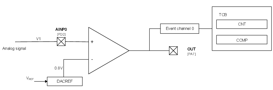
The next application example shows an implementation of duration/frequency measurement for an analog input signal, with minimal usage of microcontroller power. It uses the Event System (EVSYS) to route the signals from the AC output through an Event Channel to Timer Counter B (TCB) Event Input. To do this, the Event System must be configured properly.
The first step in the Event System configuration is to set the AC output as
Event Generator for channel 0:
Figure 2. EVSYS.CHANNEL - Set AC output
as event generator for channel 0
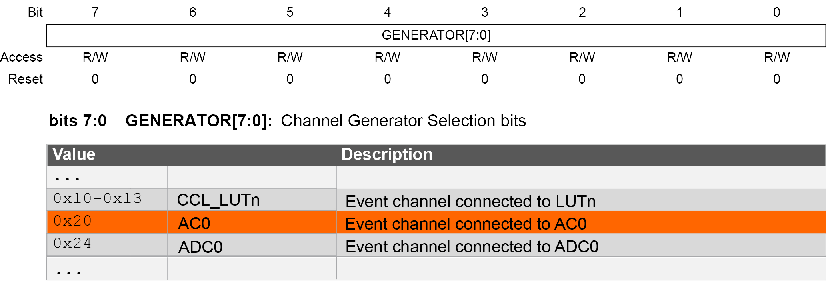
For EVSYS channel 0, the channel generator selection register must be loaded
with 0x20 to enable analog comparator as Event
Generator:
EVSYS.CHANNEL0 = EVSYS_GENERATOR_AC0_OUT_gc;
To trigger events on TCB input, the TCB Event User must be connected to channel
0:
EVSYS.USERTCB0 = EVSYS_CHANNEL_CHANNEL0_gc;
To enable pulse and period measurements, the TCB is configured in Pulse-Width Measurement mode, having as input the Event System (EVSYS), which is used to route AC output through Event channel 0 to TCB event input.
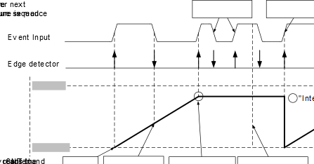
In Pulse-Width Measurement mode, the TCB will start counting when a positive
edge is detected on the event input signal. On the next falling edge, the count value is
captured. The counter stops when the second rising edge of the event input signal is
detected, and this will set the Interrupt flag. Reading the capture will clear the
Interrupt flag. When the Capture register is read, or the Interrupt flag is cleared, and
the TCB is ready for a new capture sequence. Therefore, it is recommended to read the
Counter register before the Capture register since it is reset to zero at the next
positive edge:
Figure 3. TCB - Input Capture Frequency
and Pulse-width Measurement
The following code provides a basic initialization for TCB in Pulse-Width
Measurement mode with Event System as
input:
int8_t TIMER0_init()
{

    TCB0.CTRLB = TCB_CNTMODE_FRQPW_gc;
    TCB0.EVCTRL = TCB_CAPTEI_bm;

    TCB0.INTCTRL = TCB_CAPT_bm;
    TCB0.CTRLA = TCB_CLKSEL_CLKDIV2_gc
                | TCB_ENABLE_bm
                | TCB_RUNSTDBY_bm;

}
Tip: The full code example is also
available in the Appendix section.