The EVK1100 provides 6 LEDs to design Human to Machine Interface during softwares development.

Pinout
The pinout is as follows:
| LED | Color | GPIO Name | Alternate function used |
|---|---|---|---|
| 1 | Green | PB 27 | PWM_4 |
| 2 | Green | PB 28 | PWM_5 |
| 3 | Green | PB 29 | |
| 4 | Green | PB 30 | |
| 5 | Green/Red | PB 19/PB 20 | PWM_0/PWM_1 |
| 6 | Green/Red | PB 21/PB 22 | PWM_2/PWM_3 |
Hardware Schematic
Figure 1. Mono-Color LEDs
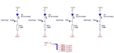
Figure 2. Bi-Color LEDs
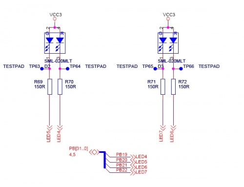
Note: The symbols of the bi-color LED 5 and
LED 6 are erroneous. Refer to Known Issues for more details
Using the PWM Channels
PWM channel are used to control LED5 and LED6. The software sequence is:
-
Configuration of the two pins of LED5 and/or LED6 as PWM channel output.
-
Control of the duty cycle of the PWM channel to change the LED color. This is done by changing the red and green ratio.