The external reset circuit is connected to the RESET pin when the external reset function is used. If the external reset function has been disabled, the circuit is not necessary. The reset switch can also be removed, if the manual reset is not necessary. The RESET pin itself has an internal pull-up resistor, hence it is optional to also add an external pull-up resistor.
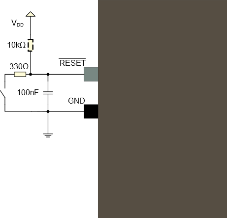
A pull-up resistor makes sure that the reset does not go low unintended causing a device reset. An additional resistor has been added in series with the switch to safely discharge the filtering capacitor, i.e. preventing a current surge when shorting the filtering capacitor which again causes a noise spike that can have a negative effect on the system.
| Signal Name | Recommended Pin Connection | Description |
|---|---|---|
| RESET | Reset low
level threshold voltage VDDIO = 1.6V - 2.0V: Below 0.33 * VDDIO VDDIO = 2.7V - 3.6V: Below 0.36 * VDDIO Decoupling/filter capacitor 100nF(1) Pull-up resistor 10kΩ(1)(2) Resistor in series with the switch 330Ω(1) |
Reset pin |
- These values are given as a typical example.
- The SAM D21 features an internal pull-up resistor on the RESET pin, hence an external pull-up is optional.