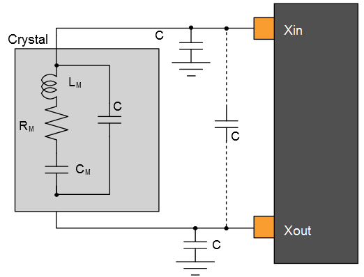
The following table describes the characteristics for the oscillator when a crystal is connected between XIN and XOUT . The user must choose a crystal oscillator where the crystal load capacitance CL is within the range given in the table. The exact value of CL can be found in the crystal datasheet. The capacitance of the external capacitors (CLEXT) can then be computed as follows:
where CSTRAY is the capacitance of the pins and PCB, CSHUNT is the shunt capacitance of the crystal.
| Symbol | Parameter | Conditions | Min. | Typ. | Max. | Units |
|---|---|---|---|---|---|---|
| fOUT | Crystal oscillator frequency | 0.4 | - | 32 | MHz | |
| ESR | Crystal Equivalent Series Resistance
Safety Factor = 3 The AGC doesn’t have any noticeable impact on these measurements. |
f = 0.455 MHz, CL = 100pF XOSC.GAIN = 0 | - | - | 5.6K | Ω |
| f = 2MHz, CL = 20pF XOSC.GAIN = 0 | - | - | 416 | |||
| f = 4MHz, CL = 20pF XOSC.GAIN = 1 | - | - | 243 | |||
| f = 8 MHz, CL = 20pF XOSC.GAIN = 2 | - | - | 138 | |||
| f = 16 MHz, CL = 20pF XOSC.GAIN = 3 | - | - | 66 | |||
| f = 32MHz, CL = 18pF XOSC.GAIN = 4 | - | - | 56 | |||
| CXIN | Parasitic capacitor load | - | 5.9 | - | pF | |
| CXOUT | Parasitic capacitor load | - | 3.2 | - | pF | |
| Current Consumption | f = 2MHz, CL = 20pF, AGC off | 27 | 65 | 85 | μA | |
| f = 2MHz, CL = 20pF, AGC on | 14 | 52 | 73 | |||
| f = 4MHz, CL = 20pF, AGC off | 61 | 117 | 150 | |||
| f = 4MHz, CL = 20pF, AGC on | 23 | 74 | 100 | |||
| f = 8MHz, CL = 20pF, AGC off | 131 | 226 | 296 | |||
| f = 8MHz, CL = 20pF, AGC on | 56 | 128 | 172 | |||
| f = 16MHz, CL = 20pF, AGC off | 305 | 502 | 687 | |||
| f = 16MHz, CL = 20pF, AGC on | 116 | 307 | 552 | |||
| f = 32MHz, CL = 18pF, AGC off | 1031 | 1622 | 2200 | |||
| f = 32MHz, CL = 18pF, AGC on | 278 | 615 | 1200 | |||
| tSTARTUP | Start-up time | f = 2MHz, CL = 20pF, XOSC.GAIN = 0, ESR = 600Ω | - | 14K | 48K | cycles |
| f = 4MHz, CL = 20pF, XOSC.GAIN = 1, ESR = 100Ω | - | 6800 | 19.5K | |||
| f = 8 MHz, CL = 20pF, XOSC.GAIN = 2, ESR = 35Ω | - | 5550 | 13K | |||
| f = 16 MHz, CL = 20pF, XOSC.GAIN = 3, ESR = 25Ω | - | 6750 | 14.5K | |||
| f = 32MHz, CL = 18pF, XOSC.GAIN = 4, ESR = 40Ω | - | 5.3K | 9.6K |
Figure 1. Oscillator Connection