This section describes the requirements for devices connected to the I2C Interface Bus.
Figure 1. I2C Interface Bus
Timing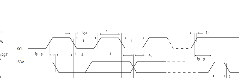
| Symbol | Parameter | Conditions | Min. | Typ. | Max. | Units | |
|---|---|---|---|---|---|---|---|
| tR | Rise time for both SDA and SCL | Standard / Fast Mode | ICb(2) = 400pF | - | 215 | 300 | ns |
| Fast Mode + |
ICb(2) = 550pF | 60 | 100 | ||||
| High Speed Mode | ICb(2) = 100pF | 20 | 40 | ||||
| tOF | Output fall time from VIHmin to VILmax | Standard / Fast Mode | 10pF < Cb(2) < 400pF | 20.0 | 50.0 | ||
| Fast Mode + |
10pF < Cb(2) < 550pF | 15.0 | 50.0 | ||||
| High Speed Mode | 10pF < Cb(2) < 100pF | 10.0 | 40.0 | ||||
| tHD;STA | Hold time (repeated) START condition | fSCL > 100kHz, Master | tLOW-9 | - | - | ||
| tLOW | Low period of SCL Clock | fSCL > 100kHz | 113 | - | - | ||
| tBUF | Bus free time between a STOP and a START condition | fSCL > 100kHz | tLOW | - | - | ||
| tSU;STA | Setup time for a repeated START condition | fSCL > 100kHz, Master | tLOW+7 | - | - | ||
| tHD;DAT | Data hold time | fSCL > 100kHz, Master | 9 | - | 12 | ||
| tSU;DAT | Data setup time | fSCL > 100kHz, Master | 104 | - | - | ||
| tSU;STO | Setup time for STOP condition | fSCL > 100kHz, Master | tLOW+9 | - | - | ||
| tSU;DAT;rx | Data setup time (receive mode) | fSCL > 100kHz, Slave | 51 | - | 56 | ||
| tHD;DAT;tx | Data hold time (send mode) | fSCL > 100kHz, Slave | 71 | 90 | 138 | ||
| Symbol | Parameter | Conditions | Min. | Typ. | Max. | Units | |
|---|---|---|---|---|---|---|---|
| tR | Rise time for both SDA and SCL | Standard / Fast Mode | Cb(2) = 400pF | - | 230 | 350 | ns |
| Fast Mode + |
Cb(2) = 550pF | 60 | 100 | ||||
| High Speed Mode | Cb(2) = 100pF | 30 | 60 | ||||
| tOF | Output fall time from VIHmin to VILmax | Standard / Fast Mode | 10pF < Cb(2) < 400pF | 25 | 50 | ||
| Fast Mode + |
10pF < Cb(2) < 550pF | 20 | 30 | ||||
| High Speed Mode | 10pF < Cb(2) < 100pF | 10 | 20 | ||||
| tHD;STA | Hold time (repeated) START condition | fSCL > 100kHz, Master | tLOW-9 | - | - | ||
| tLOW | Low period of SCL Clock | fSCL > 100kHz | 113 | - | - | ||
| tBUF | Bus free time between a STOP and a START condition | fSCL > 100kHz | tLOW | - | - | ||
| tSU;STA | Setup time for a repeated START condition | fSCL > 100kHz, Master | tLOW+7 | - | - | ||
| tHD;DAT | Data hold time | fSCL > 100kHz, Master | 9 | - | 12 | ||
| tSU;DAT | Data setup time | fSCL > 100kHz, Master | 104 | - | - | ||
| tSU;STO | Setup time for STOP condition | fSCL > 100kHz, Master | tLOW+9 | - | - | ||
| tSU;DAT;rx | Data setup time (receive mode) | fSCL > 100kHz, Slave | 51 | - | 56 | ||
| tHD;DAT;tx | Data hold time (send mode) | fSCL > 100kHz, Slave | 71 | 90 | 138 | ||
1. These values are based on simulation. These values are not covered by test limits in production.
2. Cb = Capacitive load on each bus line. Otherwise noted, value of Cb set to 20pF.