The main objective of this hands-on Lab is to build a simple example using the Event System, RTC periodic interrupt timer and some GPIO. The example involves configuration in the DASHBOARD, PINMUX, CLOCKS config and EVENTS configurator screens.
Our basic use case is to generate event triggers using the SW0 button press event and Periodic Interrupt from internal RTC running on 2 Hz frequency. Given the core independent nature of these peripherals with the event system, once it is configured, no further code needs to be run.
- 1.Create new project for ATtiny817 Xlained Pro
- 2.Configure EVENTS
- 3.Configure CLOCKS: 1 kHz CLK_RTC, for simple calculation of 2 Hz out
- 4.Configure Dashboard: Enable EVOUT signals and RTC Periodic Interrupt timer
- 5.Configure PINMUX: SW0, SW1 and LED pins
- 6.Export, run and visualize the output in Atmel Studio IDE
Setup and Configure the Project
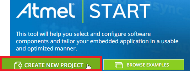
- 1.
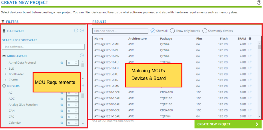
Info: START’s CREATE NEW PROJECT allows you to filter by both SW and HW requirements, then select a microcontroller (MCU) device (and board). On the left-hand side you will enter MCU Requirements, while on the right-hand side you will see the MCU’s, Devices and Boards, which match these requirements. Note the MCU requirements are both HARDWARE and SOFTWARE, i.e., that a given MIDDLEWARE works on that MCU.
- 2.
Todo:
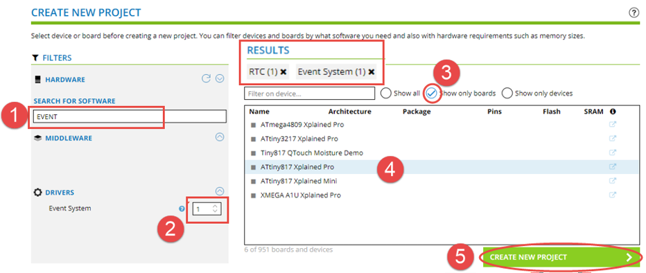
- 1.In the SOFTWARE SEARCH, search “EVENT”
- 2.Increment the number required to 1. (You will see it in the RESULTS list.) Do the same for RTC.
- 3.Check the Show only boards check box in the MCU filter side.
- 4.Select ATtiny817 Xplained Pro
- 5.Finally, click on CREATE NEW PROJECT.
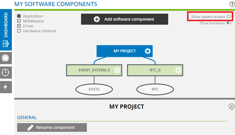
 Result: Project opens in DASHBOARD view. EVENT SYSTEM and RTC drivers have been added.Tip: Access the following video fore more details on how to configure the DASHBOARD.
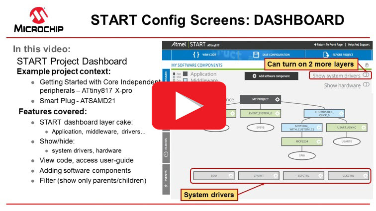
- 3.
Todo: Uncheck Show system drivers to simplify the view.
- 4.
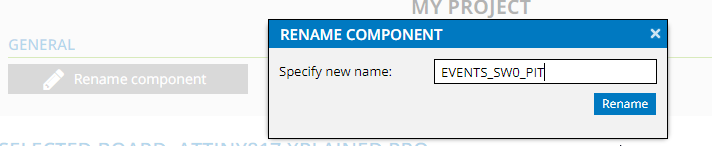
Todo: Select the project named “MY PROJECT” then click rename.
 Tip: When START projects are exported, the default project name is the name of the project component.
Event System Configuration
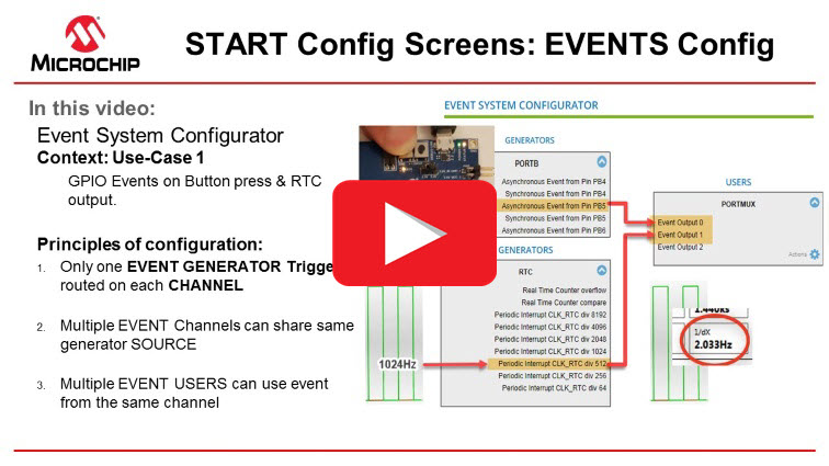
The Event System (EVSYS) enables direct peripheral-to-peripheral signaling. It allows a change in one peripheral (the Event Generator) to trigger actions in other peripherals (the Event Users) through Event Channels without using CPU. The CPU continues to execute instructions while the channel system operates in parallel.
The START as a code configurator tool supports two ways to configure the Event System, i.e., via General UI for EVENT_SYSTEM_0 available on project dashboard or via Event System Configurator screen.
In the described use case, our PERIPHERAL EVENT GENERATOR triggers are SW0 on PB5, and the RTC Periodic Interrupt timer.
Let’s go straight to the EVENTS tab:
- 1.
Todo: Click on the EVENTS tab (
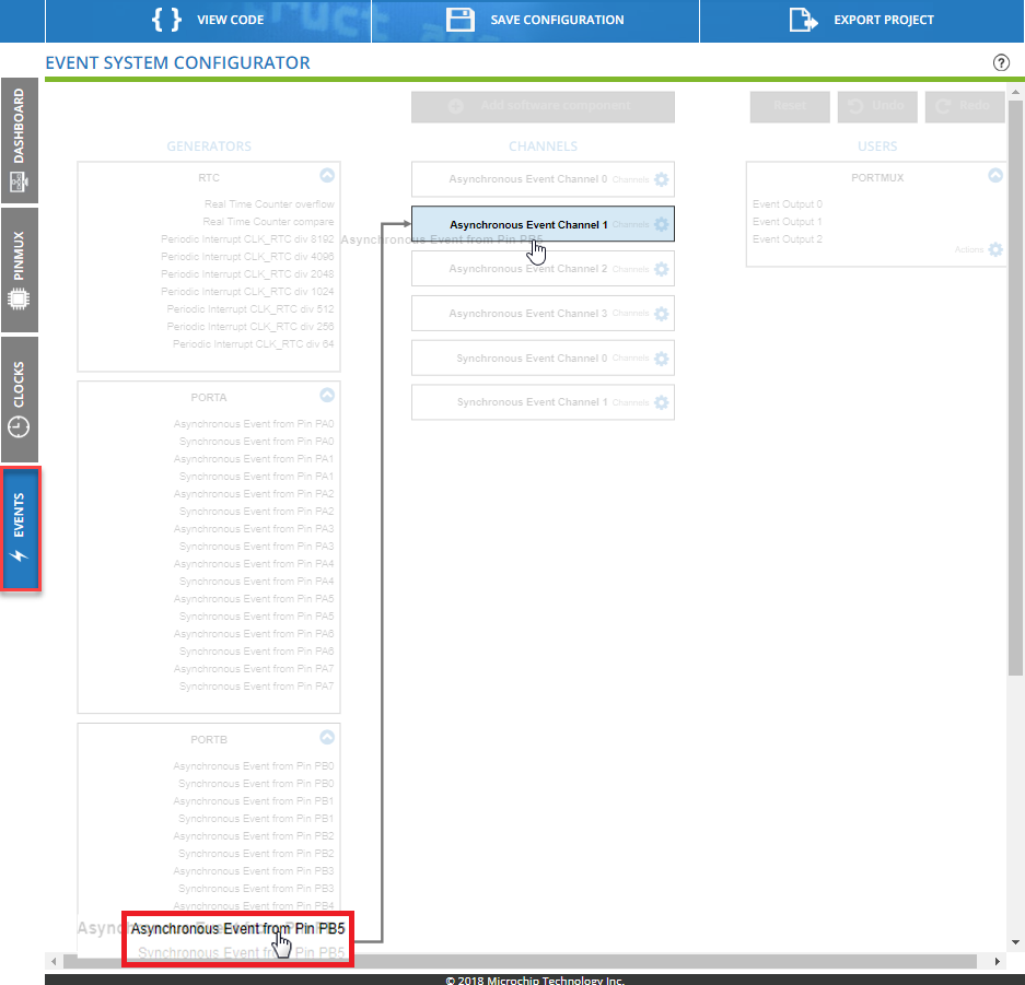
 symbol, on a low-resolution screen). Info: User Button (SW0) is connected to PB5.
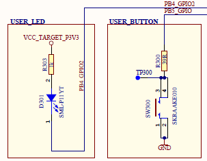 Tip: Since a button press is asynchronous to the MCU and the SW0 is connected to PB5, the GENERATOR trigger will be Asynchronous Event from PB5.
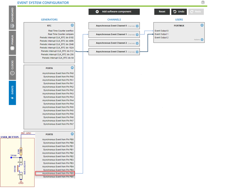
 - 2.Todo: Find an appropriate EVENT CHANNEL for Asynchronous Event from PB5. Using a mouse click + hold or click + drag, then make this connection.Once the GENERATOR (Async Event from Pin PB5) is connected to the corresponding CHANNEL (Async Event Channel 1), it’s time to go further to connect the CHANNEL to the corresponding USERS.
- 3.
Todo: Connect Async EVENT Channel 1. In turn Async Event Channel 1 to USER, PORTMUX Event Output 0.Figure 1. Events configuration of SW0 on PB5
 Info:
Info:The Periodic Interrupt Timer (PIT) can generate an interrupt on every nth clock period (n can be selected from the value 4 to 32768) and moreover the PIT uses the same clock source (CLK_RTC) as the RTC function.
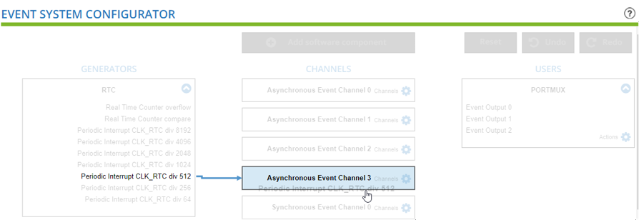
RTC PIT: Our objective is a 2 Hz signal. We will set the RTC_CLK to 1024; an appropriate GENERATOR trigger is Periodic Interrupt CLK_RTC div 512.
- 4.Connect GENERATOR (Periodic Interrupt CLK_RTC div 512) to a suitable
event CHANNEL (Async Event Channel 3). (Long click
or start dragging to see possible channels). In turn
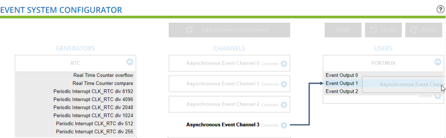
connect the CHANNEL output (Async Event Channel 3) to the USER
(PORTMUX Event Output 1).
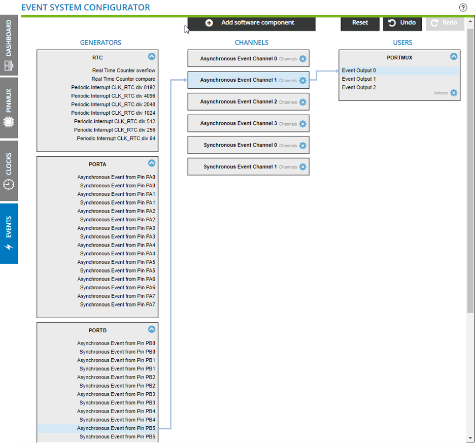
 Result: The EVENT SYSTEM CONFIGURATOR is now set up is as follows:
- 1.A button press generates an Asynchronous Event from Pin PB5, triggering PORTMUX Event Output 0 (via Async Event Channel 1).
- 2.An RTC Periodic interrupt CLT_RTC div 512, triggers PORTMUX Event Output 1 via (Async Event Channel 3).
- 5.
Warning: We will need to separately enable components and signals used in the DASHBOARD. (RTC_CLK can be configured either in the DASHBOARD or in CLOCKS config).
CLOCKS, DASHBOARD and PINMUX Configurators
Minor configuration updates are needed in a few of the other configuration windows.
CLOCKS, DASHBOARD and PINMUX Configurators
Atmel START provides you with an independent configurator to configure, control, distribute and pre-scale the clock signals from the available oscillators by supporting both internal and external clock sources.
- 1.
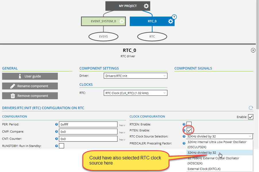
Todo: Click on the RTC clock configuration gear. Select 32 KHz divided by 32 as the RTC Clock Source Selection.
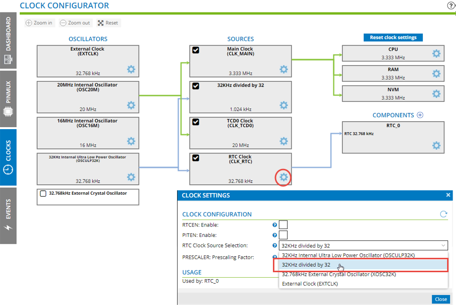 Result: The RTC clock is now set to 1 Khz. Selecting the RTC shows its clock connections.
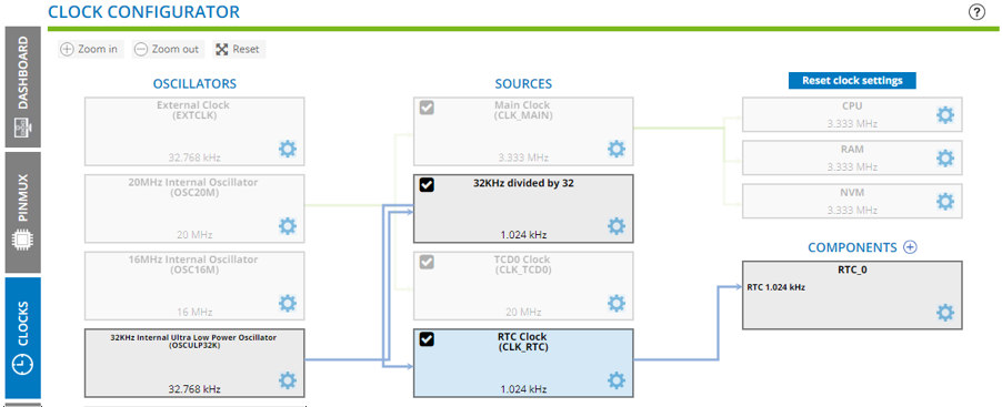
DASHBOARD Configuration
For our two components, the RTC and Event System, we now need to enable what we have used.
- 1.
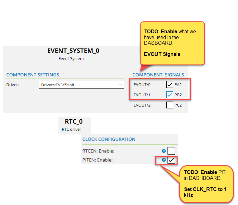
Todo: Click on RTC_0 component, then PITEN: Enable
- 2.
Todo: Enable the EVENT_SYSTEM_0 Component Signals EVOUT/0 and EVOUT/1:
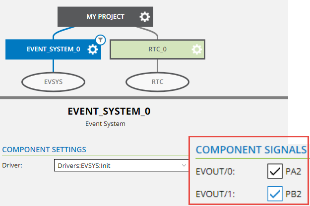 Tip: The EVENT_SYSTEM_0 DASHBOARD exposes a low-level view of the Event System configuration, which can help to understand the generated code, to initialize the event system. View the Event System generated code by clicking VIEW CODE, then navigating to ./src/evsys.cFigure 2. DASHBOARD view of EVENT SYSTEM matches code generated, SW0 Event configuration highlighted
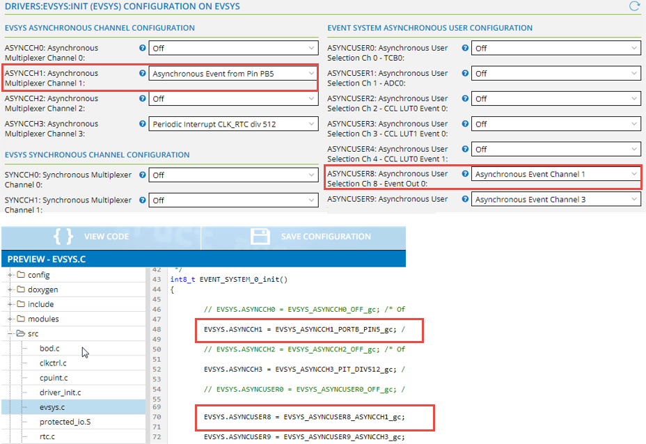
PINMUX Configuration
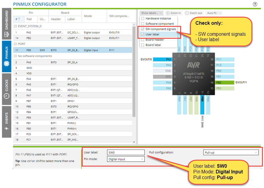
The EVOUT pins need no further configuration. All that is required is to configure the SW0 pin.
- 1.
Todo: Configure PB5 as a Digital Input, enable Pull-ups.
Export, Run and Visualize
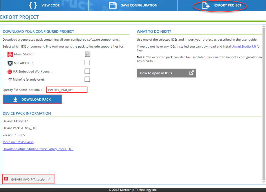
Here we reach to the final sub-section where we will be exporting the project (.atzip format) from START and import it into Atmel Studio IDE. After importing the project we will compile, run and visualize the output in serial port terminal via the Virtual COM port.
- 1.
Todo: Go to EXPORT PROJECT, name the project “EVENTS_SW0_PIT”, then click DOWNLOAD PACK and import the project into Atmel Studio 7.
 Tip: Ways to open the Import Atmel Start Project Wizard in Atmel Studio 7:
- 1.Drag and drop .atzip onto Atmel Studio 7
- 2.
- 3.Double-click on the .atzip file, this will open a new instance of Atmel Studio 7
- 2.
Todo: Using the Import Atmel Start Project Wizard, create a new project in Atmel Studio 7.
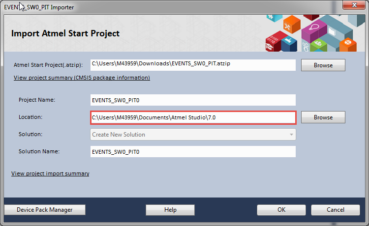 Tip: The default name matches the name of the .atzip (named in the Export Project window)Result: Project is created. Note that main.c is empty, besides a call to a function which initializes the configured peripherals. The configuration of the Event System can be seen in evsys.c.
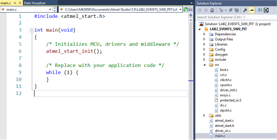
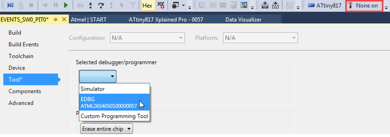
- 3.
Todo: Associate the project with the connected debugger.
- 4.
Todo: Click Start Without Debugging (
 ) to program the MCU.
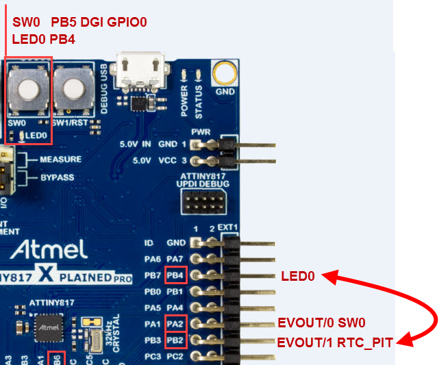
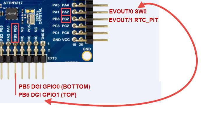
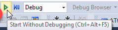 Info: The image below shows all the relevant connections on the ATtiny817 Xplained Pro.
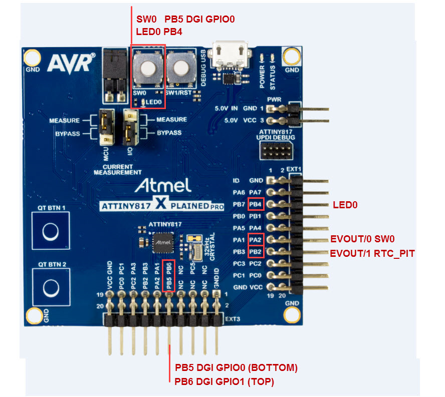
- 5.
Todo:
Verify 2 Hz PIT EVENT using the LED0
Connect:PB2 EVOUT/1 RTC_PIT to PB4 LED0
 Result: LED should flash at 2 Hz.
 - 6.
Todo:
Verify 2 Hz PIT EVENT using the Data Visualizer
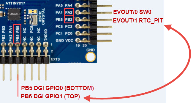
Connect: PB6 DGI GPIO1 to PB2 EVOUT/1 RTC_PIC
- 7.
Todo:
- 1.First connect to DGI (Data Gateway Interface)
- 2.Enable the DGI GPIO check box (if not already enabled)
- 3.Double-click to add a Graph
- 4.Drag the GPI GPIO1 onto a new plot (Careful: Picture shows GPIO0)
- 5.Click Start
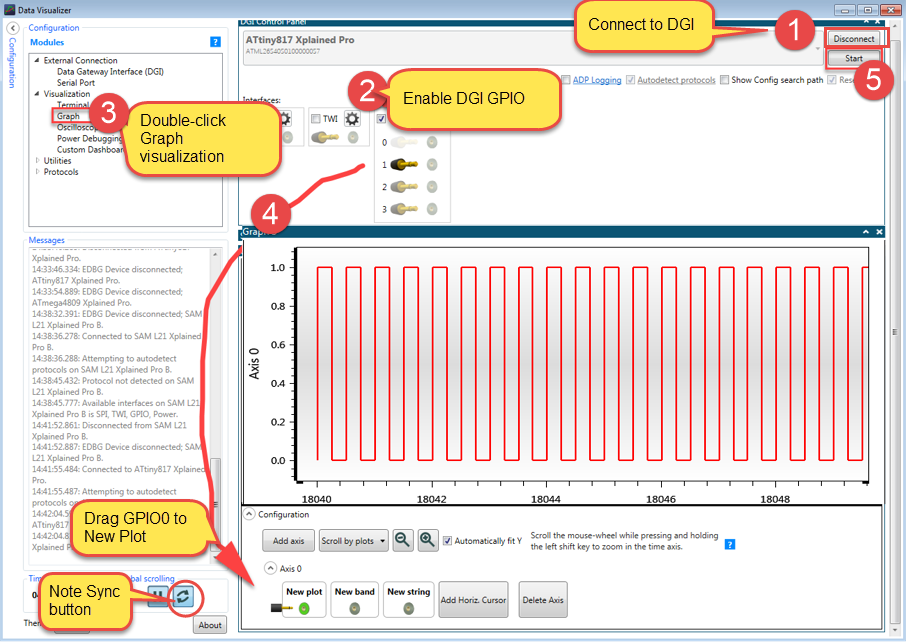 Tip: Later when we add a second graph, you may need to click the sync button.
 - 8.
Todo:
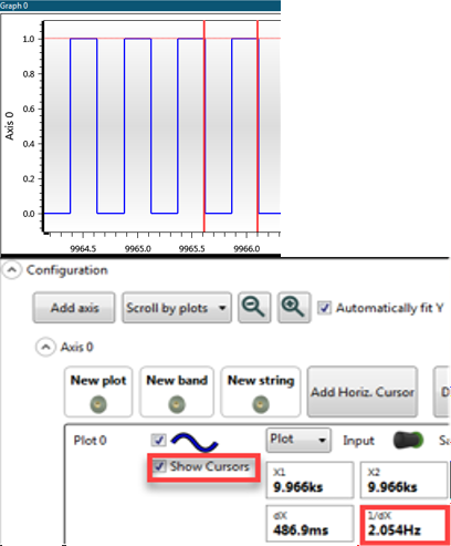
- 1.Press SPACE bar to pause the graph
- 2.Click Show cursors
- 3.Align cursors to measure frequency
- 9.
Todo:
Verify Event on SW0 press
Connect: PB6 (DGI GPIO1) to PA2 SW0 (EVOUT/0)
- 10.
Todo:Data Visualizer:
- 10.1.Minimize configuration of graph
- 10.2.Double-click to add a second graph
- 10.3.Drag the GPI GPIO0 onto a new plot
- 10.4.SPACE bar to start graph again
- 10.5.Start pressing SW0
Result: The EVOUT/0 corresponds to stimulus on PB5 (SW0).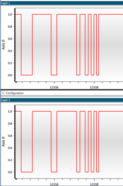
LAB 2 Summary
This is the end of LAB 2. To summarize, we setup and added the Event system according to the required use case. There were minor configurations needed for the CLOCK, DASHBOARD and PINMUX. For example, in the DASHBOARD we enabled the EVENT OUT signals, as well as the RTC PIT, while the PINMUX pin PB5 was configured as a digital input with pull-up enabled.
The project was exported, run and verified using the Data visualizer.