Re-configuring the project from LAB2, the logic peripheral is added to the project. Minor modifications are made to all the configuration screens used in LAB2 in addition to using the CCL (Logic) configurator.

The Custom Configurable Logic (CCL) is a programmable logic peripheral that can be connected to device pins and other internal peripherals and serves as a “Glue Logic” between the device peripherals and internal devices. If logic can be handled in hardware, it can be much faster than a software implementation of the same logic. In this way, it may be possible to make time critical parts of the application CPU independent. This lab will focus on the CCL peripheral, which due to its unique nature has its own config screen.
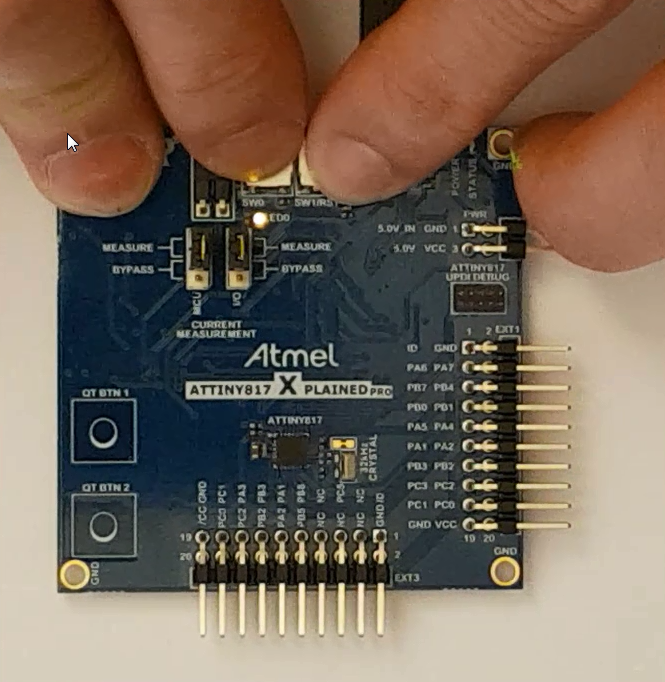
Our use case, to get to know the Custom Configurable Logic (CCL) peripheral, is to turn on the LED only when both SW0 and SW1 on the kit are pressed.
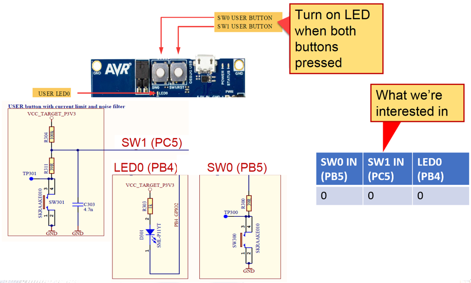
- SW0 (PB5): When SW0 switch is pressed, PB5 pin will be pulled low. (No pull-ups on schematic)
- SW1 (PC5): When SW1 switch is pressed, PC5 pin will be pulled low. (Is external pull-up on schematic).
- LED0: When driving PB4 low, LED will be turned on.
The following sections will take you through how to configure the pins for the switches and LED using the START code configurator and using the CCL driver to drive the LED ON when both switches are pressed.
Reconfiguration of Project to setup CCL Use Case 1
This section deals with some details on how to reconfigure the project via Atmel Studio IDE.
- 1.
Todo: Click the Reconfigure Atmel START Project button (
 )
)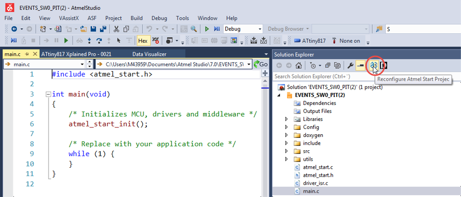 Tip: After you have reconfigured a project once, the START window will stay open so further changes can be done quickly.Result: After selecting the “Reconfigure Atmel START project” you should see the Studio as per the below figure:
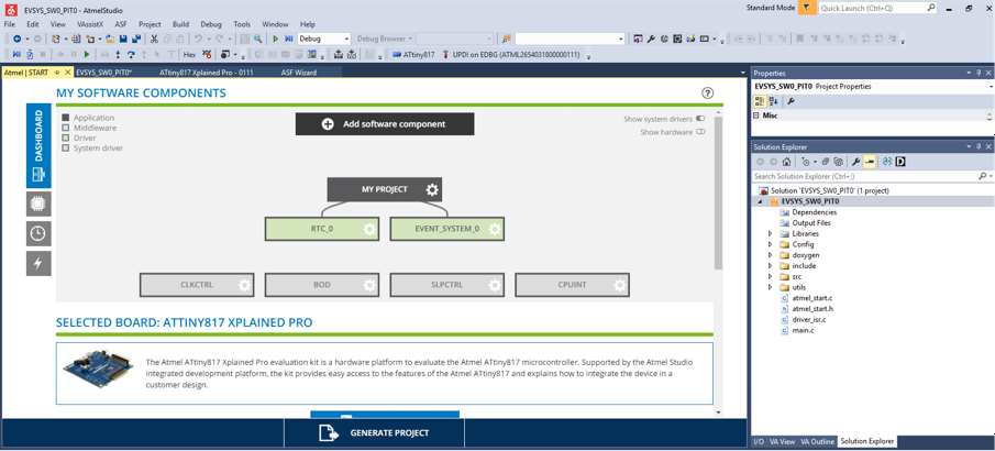
- 2.
Todo: Add the Custom Configurable Logic (CCL) as a component to START
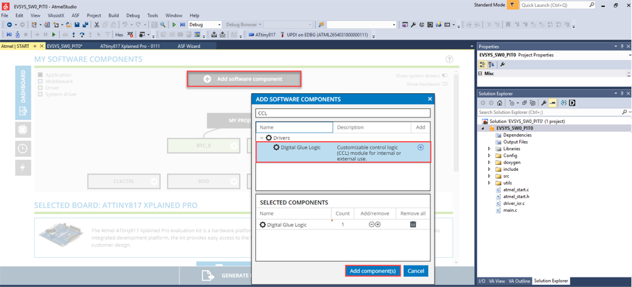 Result: CCL is added to START.
Custom Logic Configuration: LUT inputs (Event input)
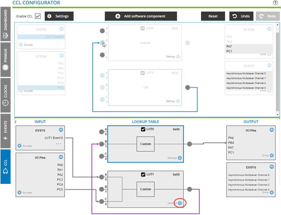
Let’s go straight to the logic tab.
- 1.
Todo: Click on the CCL tab.
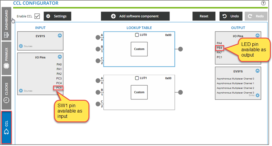 Info: Note the location of PC5 (SW0) and PB4 (LED) pins.Tip: You can add software components directly from this screen (as with the Event System).
 - 2.
Todo: Find possible connections for PC5 and PB4 by long-clicking on each pin.
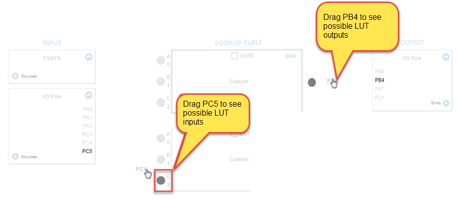 Result: The only possible connections of each are respectively:
- 1.PC5 (SW1) to LUT1:C2
- 2.PB4 to LUT0 output
- 3.
Todo: Make these connections. Also click to enable both LUT0 and LUT1.
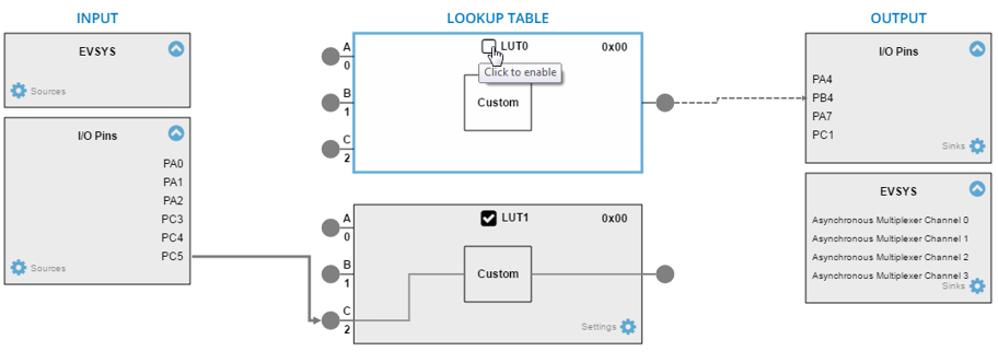 Info: PIN PB5 is not available as a logic input. However, we have already configured an event associated to this pin. We will need to modify the Event System configuration to use the Event System output as an input to “Look Up Table 1 (LUT1)”.Tip: Generating an Event Out on LUT1 will make it easier to configure the logic configuration needed.
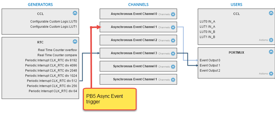
- 4.
Todo:
- 1.Click + hold (or drag) to see possible connections for “Async Event Channel 1”
- 2.Note that LUT1 IN_A is an option
- 3.Make this
connection
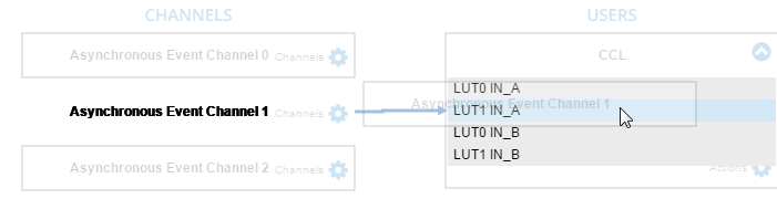
Result: The Async Event Channel 1 is now connected to two event users.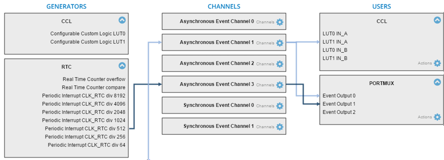 Tip: Principles of Event System Configuration:
- 1.Only one EVENT GENERATOR trigger routed on each CHANNEL
- 2.Multiple EVENT Channels can share same generator SOURCE
- 3.Multiple EVENT USERS can use an event from the same channel
- 5.
Back in the Logic (CCL) screen, LUT1 Event 0 now shows up as an Input for LUT1.
Todo: Click + drag to make the connection to LUT1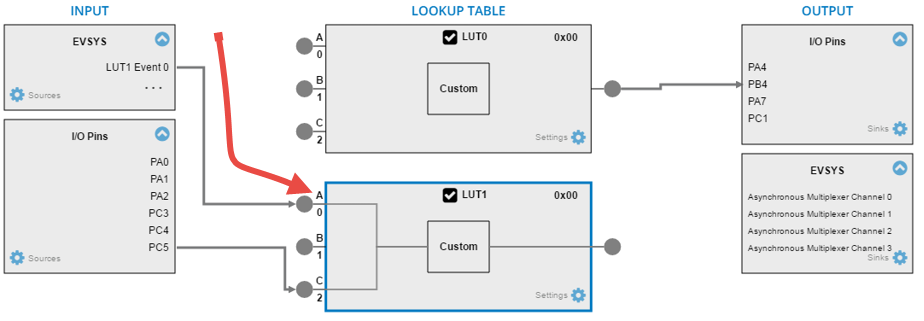
Next we will connect the two LUT’s together in order to wire the connections all the way through.
- 6.
Todo: Click + drag to connect the output of LUT1 to ‘B’ input of LUT0 as shown below:
 Warning: When cascading two Lookup Tables, make sure the Output Enable check box is checked.
 - 7.
Todo: Click on the LUT1 configuration gear, then check OUTEN: Output Enable.
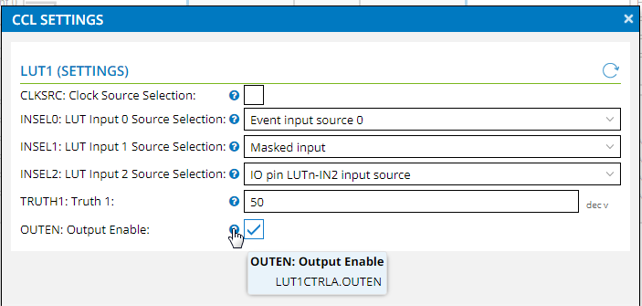 Info: All the wires are now connected. What remains is to configure the logic to function as needed.
Truth Table Logic Input
According to our use case we need output of ‘0’ (LED
ON) only when both inputs are ‘0’, in other words SW0 and SW1 must
be pressed. In the previous section all the Lookup Table (LUT) wiring was done, for
example, the LUT inputs, connection between the LUTs, as well as the LUT output,
were configured.
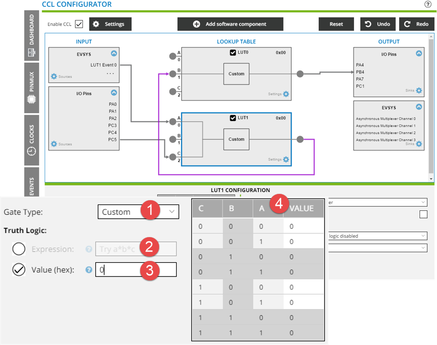
- 1.Gate Type selection, selecting custom exposes the other options.
- 2.Truth Logic Expression.
- 3.Truth Type Value (Hex).
- 4.Direct editing of logical Truth Table.
| SW0 IN (PB5) | SW1 IN (PC5) | LED0 (PB4) |
|---|---|---|
| 0 | 0 | 0 |
| SW0 IN (PB5) LUT1 A |
SW1 IN (PC5) LUT1 C |
LED0 (PB4) LUT1 VALUE = LUT0 VALUE |
|---|---|---|
| 0 | 0 | 0 |
LUT0: Let us use LUT0. Simply use LUT0 as a pass through, i.e. an
input of ‘1’, gives and output of ‘1’, and an
input of ‘0’ gives an output of ‘0’.
00,
01, 10, 11) then defining the
required LUT1 VALUE for each.
| LUT1 Required Truth Table | LUT0 Required Truth Table | ||||||||
|---|---|---|---|---|---|---|---|---|---|
| SW0 IN (PB5) LUT1 A |
SW1 IN (PC5) LUT1 C |
LED0 (PB4) LUT1 VALUE |
|
||||||
| 0 | 0 | 0 | |||||||
| 0 | 1 | 1 | |||||||
| 1 | 0 | 1 | |||||||
| 1 | 1 | 1 | |||||||
With the required Truth Tables for LUT0 and LUT1 clear, the various methods of obtaining this required output will be explored.
Gate Type Selection
Since we wish to turn on the LED when both SW0 and SW1 are pressed, let’s start with a simple AND gate.
- 1.
Todo: Click on LUT1, then select Gate Type as AND
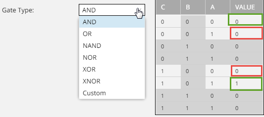 Info: The LUT1 B column is grayed out since it is not used.Result: Two of the entries in the VALUE column are correct (in the green box), while the values indicated in RED are wrong.
 - 2.
Todo: Again, for LUT1, select Gate Type as OR
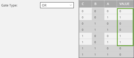 Result: The value output of the Truth Table now matches the requirements for LUT1.
 - 3.
Todo: Click on LUT0 and select an appropriate gate type for the pass-through Truth Table of LUT0
 Result: Either AND or OR gates give the required Truth Table.
Truth Logic: Expression
One of the custom logic input types is entering a logical expression. To enter a logical expression, ensure that Custom is selected as Gate Type and click on the Expression check box.
- 1.
Todo: Click on LUT1, selectGate Type as Custom, then check Expression
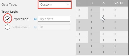 Tip: Look for question marks if you are unsure about what to enter in a field.
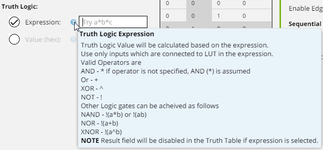
For the sake of symmetry, let’s repeat the process described in the Gate Type Selection section. Since we wish to turn on the LED when both SW0 and SW1 are pressed, let’s start with a simple AND gate.
- 2.
Todo: Following the key, enter: A*C, to represent A AND C
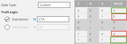 Result: As expected, the result is the same as if we had selected an AND gate.
 - 3.Let’s enter the expression corresponding to the next logic box in the list, the
OR gate, represented with a: “+”.Todo: Enter: A+C, to represent A OR C
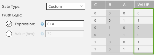 Result: The value output of the Truth Table now matches the requirements for LUT1.
 - 4.
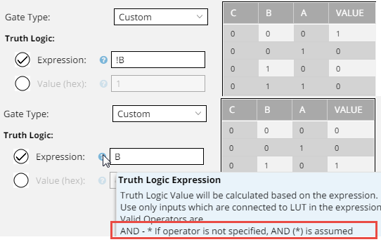
Todo: Select an appropriate expression for the pass-through Truth Table of LUT0.Info: Although there is only one input in the Gate Type Selectionsection, it is possible to enter B, or !B. B is the expression needed.
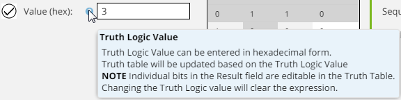
Truth Type Value (Hex)
Another one of the custom input types is directly entering the required hex output value. To enter a hex Value, ensure that Custom is selected as the Gate Type.
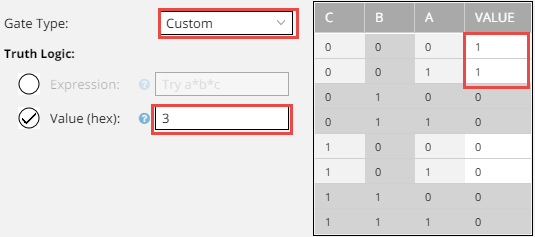
- 1.
Todo: Enter the Hex values corresponding to the required Truth Table outputs.
LUT1 Required Truth Table LUT0 Required Truth Table SW0 IN (PB5) LUT1 A
SW1 IN (PC5) LUT1 C
LED0 (PB4) LUT1 VALUE
LUT0B LUT0 Value 0 0 1 1 0 0 0 0 1 1 1 0 1 1 1 1 Result: Our required Truth Table results for LUT1 and LUT0, are 32 and 4 respectively.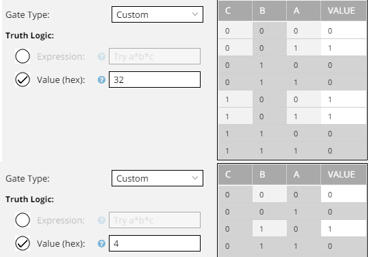 Result: Using Gate Types of AND (LUT0) OR (LUT0) gives us a configuration matching the requirements of our use case.
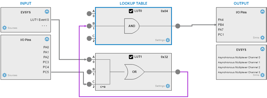 Tip: Selecting Gate Types that match the logical expressions allow the configuration to be viewed as a schematic – the most immediately readable input format.
The various methods of logic input to the Lookup Tables (LUTs) have now been explored. There are a couple of pins that need to be configured before we can generate the project
PINMUX Input
Referring to the start of LAB 3, the following note was made regarding the required pin configuration:
- SW0 (PB5): When SW0 switch is pressed, PB5 pin will be pulled low. (No pull-ups on schematic)
- SW1 (PC5): When SW1 switch is pressed, PC5 pin will be pulled low. (Is external pull-up on schematic).
- LED0: When driving PB4 low, LED will be turned on.
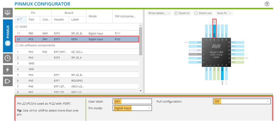
- 1.
Todo: Configure pin PC5 as indicated:
User label: SW1, Pin mode: Digital input, Pull configuration: OFF.
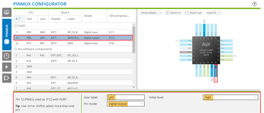
- 2.
Todo:
Configure pin PB4 as indicated:
User label: LED, Pin mode: Digital output, Initial level: High.
- 3.
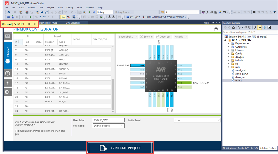
Todo: User Labels: Label PA2: EVOUT_SW0 and PB2: EVOUT1_RTC_PIT:
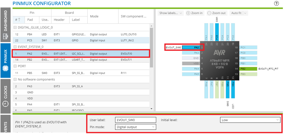
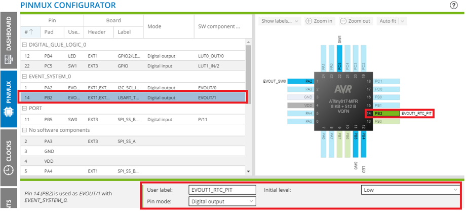 Tip: Turning on only User Labels allows us to get a summary of pins used in our application.
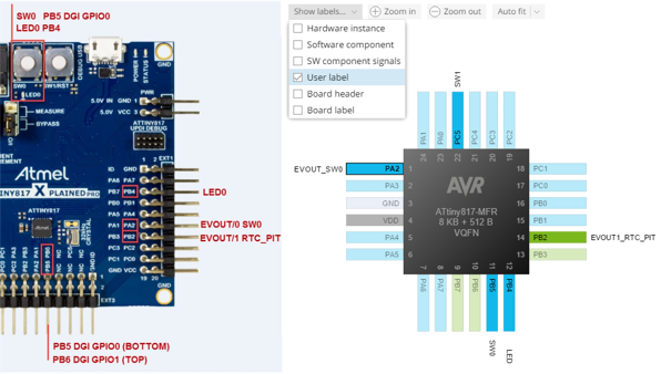
Generate and Test
Before we generate the project, let’s make one manual change to the configuration of one of the peripherals.
- 1.
Todo:
- 1.Open ./src/rtc.c
- 2.Toggle off the comment on the last line, disabling the PIT
interrupt, change the ‘
0’ to a ‘1’, then delete the comment since it is now invalid.
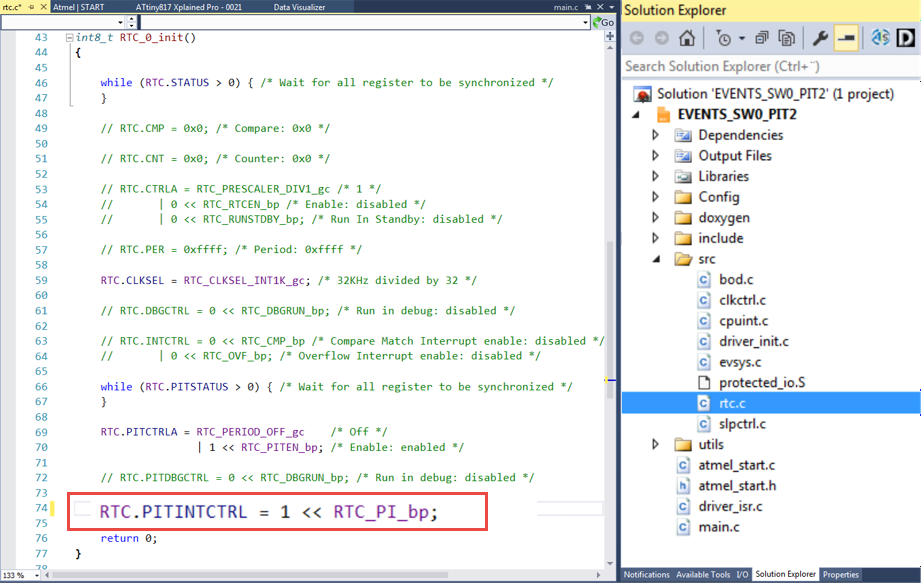 Tip: It is generally better to delete comments, than risk that they get out of date.
Now let’s generate the code and see what happens when we modify the generated files.
- 2.
Todo: Click on the Atmel START tab, then GENERATE PROJECT (or click on the Re-configure Atmel START Project Button, to
bring the tab into focus).
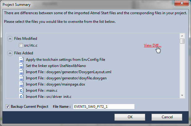
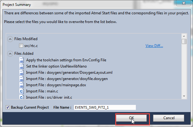
 Result: You will see a downloading content screen, followed by a Project Summary. The Project Summary will indicate that src/rtc.c has been modified. Giving the option to View Diff…
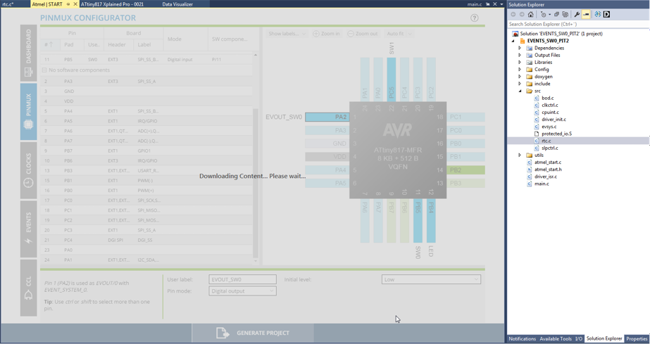
- 3.
Todo: Click on the View Diff… option.
 Result: WinMerge is opened, highlighting the change made to the generated file. You can decide to keep the change or discard it.
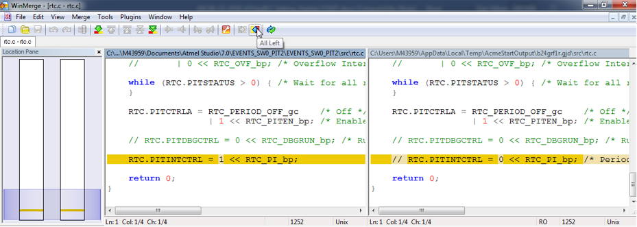 Tip: Note the file paths: the file on the left is the one in your project, the one on the right is the new configuration file being downloaded from START.
 - 4.
Todo: Revert to the configuration in the file downloaded from START by clicking the All Left button.Result: A pop-up will be displayed saying that the files are identical.
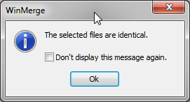
- 5.
Todo: Click OK to complete the project generation.
- 6.
Todo: Double-click on main.c if not already open. Notice that besides some initialization code, no other code runs. Click Start Without Debugging to program the part and start it running.
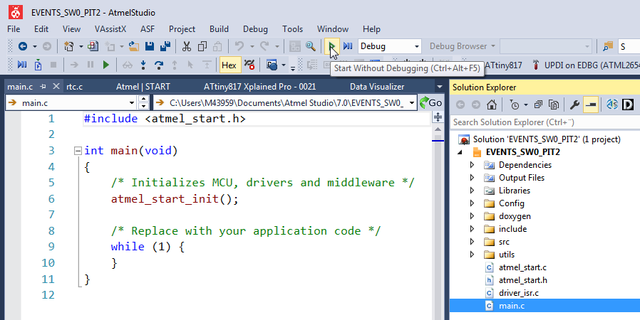 Result: LED0 now comes ON only when both SW0 and SW1 are pressed.