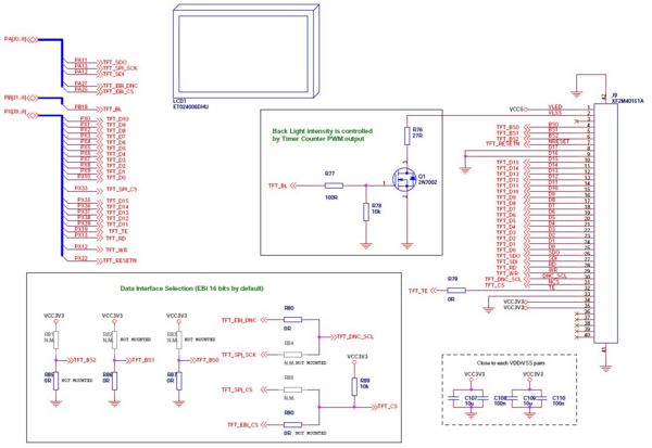
The ET024006DHU LCD is a QVGA (320x240) display with up to 18-bit resolution from Emerging Display Technologies Corporation. The display is connected to the EBI of the UC3A but can also be used with the SPI. The backlight of the display is controlled by a PWM module of the UC3A (pin PB18, channel PWM[6]). A tearing signal can be used to synchronize a display content update with a write to a frame buffer. This is especially useful for showing video frames. The reset line of the LCD is connected to an extra pin of the UC3A and not to the board reset because it needs a special power up sequence. A detailed overview over the display connection is available in the schematics.
EBI configuration
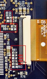
The EBI solution is much faster than SPI but since the UC3A memory management unit does not offer memory to memory copying an update of the whole display content form a frame buffer in memory can take quite some CPU time. Anyhow a trick to do memory to memory copies can be done by using a USART module in loopback mode. The USAR module offers DMA for sending and receiving data and therefore able to do the work without CPU intervention. The display content can also be updated directly without the need of an extra memory that contains a frame buffer. This approach may use more CPU time than the extra frame buffer with DMA, since the display memory is only addressable by configuring registers first. Especially for writing single pixels offers the extra frame buffer a performance gain. The display can be in either command or parameter mode and this is signaled by an extra data line. This line is connected to a higher address pin (address line ADDR[21]) of the UC3A in order to let the SMC handle the toggling and because of that get a faster access time. The display uses the EBI chip select signal 0 and therefore starts the address space at 0xC0000000. In order to read/write a command use the address 0xC000_0000. A parameter can be read/written by using address 0xC0200000. In order to use the LCD with the EBI in 16-bit per pixel mode or in 18-bit per pixel mode it is necessary to change some of the resistors marked in the image. For more details on the configuration take a look at the schematics and the display user guide.
SPI configuration
The SPI connection is only efficient when an extra frame buffer in the memory and the DMA functionality of the module is used. The CPU writes to the frame buffer and initiates a DMA transfer with the SPI module. This approach updates the display content without a lot of CPU intervention. A disadvantage of the SPI solution is that only low frame rates are achievable. Because of that animations and videos may not work with the desired frame rate. In order to use the LCD in SPI mode it is necessary to change some of the resistors marked in the image. For more details on the configuration take a look at the schematics and the display user guide.
The display is connected to the SPI0 module. On this SPI bus is also the DataFlash and SD-MMC interface. Because of that the bandwidth is further decreased if any of the other devices on the bus need to transfer any data.