The figure below shows a detailed block diagram of the timer/counter.
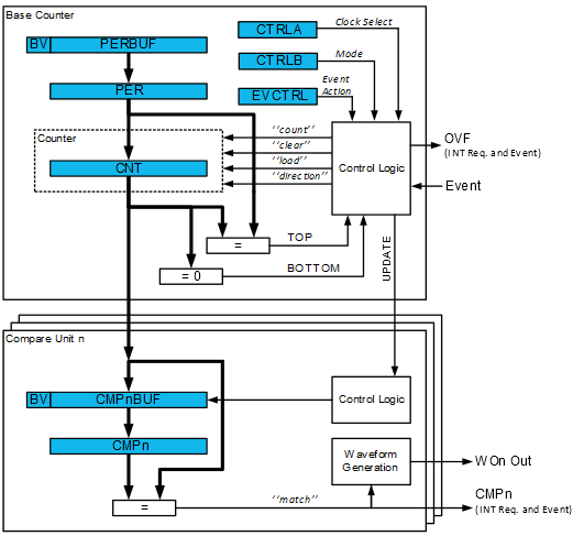
The Counter register (TCAn.CNT), Period and Compare registers (TCAn.PER and TCAn.CMPm) and their corresponding buffer registers (TCAn.PERBUF and TCAn.CMPBUFm) are 16-bit registers. All buffer registers have a Buffer Valid (BV) flag that indicates when the buffer contains a new value.
During normal operation, the counter value is continuously compared to zero and the period (PER) value to determine whether the counter has reached TOP or BOTTOM.
The counter value is also compared to the TCAn.CMPm registers. These comparisons can be used to generate interrupt requests. The Waveform Generator modes use these comparisons to set the waveform period or pulse width.
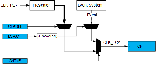
A prescaled peripheral clock and events from the Event System can be used to control the counter as shown in the figure below.