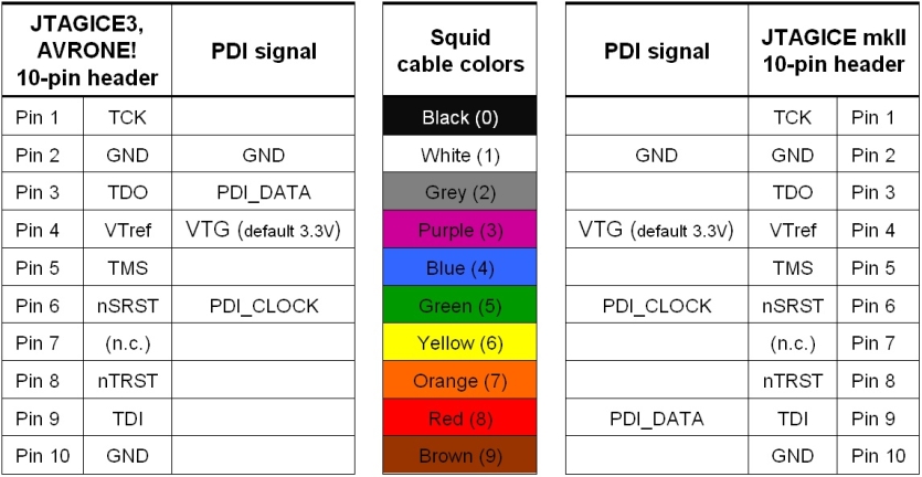
The Atmel ATxmega128B1 can be programmed and debugged by connecting an external programming and debugging tool to the PDI header. The header has a standard PDI programmer pinout (refer to online help in Atmel Studio), and tools such as JTAGICE3, AVR ONE! or JTAGICE mkII can thus be connected to the PDI header. If it is desired to use PDI for programming and debugging an adapter must be used:
-
(Dark blue) debugWIRE, SPI, PDI, aWire Adaptor for JTAGICE3, ref. A08-0735
-
(Green) Standoff Adaptor nr.3 JTAG/ISP for AVR ONE!, ref. A08-0254
-
(White) Xmega PDI Adaptor for JTAGICE mkII, ref. A09-0412
|
Pin |
PDI1
|
JTAGICE3 | AVRONE! | JTAGICE mkII |
|---|---|---|---|---|
|
1 |
PDI_DATA |
debugWIRE, SPI, PDI, aWire adaptor ref. A08-0735. Color: dark blue |
Standoff adaptor nr.3 JTAG/ISP ref. A08-0254. Color: green |
Xmega PDI adaptor ref. A09-0412. Color: white |
|
2 |
VTG (default 3.3V) |
|||
|
3 |
||||
|
4 |
||||
|
5 |
PDI_CLOCK |
|||
|
6 |
GND |