Figure 1. Clock Timing
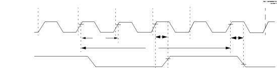
Note: See table below.
| Standard Operating Conditions (unless otherwise stated) | |||||||
|---|---|---|---|---|---|---|---|
| Param No. | Sym. | Characteristic | Min. | Typ. † | Max. | Units | Conditions |
| ECL Oscillator | |||||||
| OS1 | FECL | Clock Frequency | — | — | 500 | kHz | |
| OS2 | TECL_DC | Clock Duty Cycle | 40 | — | 60 | % | |
| ECM Oscillator | |||||||
| OS3 | FECM | Clock Frequency | — | — | 8 | MHz | |
| OS4 | TECM_DC | Clock Duty Cycle | 40 | — | 60 | % | |
| ECH Oscillator | |||||||
| OS5 | FECH | Clock Frequency | — | — | 64 | MHz | |
| OS6 | TECH_DC | Clock Duty Cycle | 40 | — | 60 | % | |
| LP Oscillator | |||||||
| OS7 | FLP | Clock Frequency | — | — | 100 | kHz | Note 4 |
| XT Oscillator | |||||||
| OS8 | FXT | Clock Frequency | — | — | 4 | MHz | Note 4 |
| HS Oscillator | |||||||
| OS9 | FHS | Clock Frequency | — | — | 20 | MHz | Note 4 |
| Secondary Oscillator | |||||||
| OS10 | FSEC | Clock Frequency | 32.4 | 32.768 | 33.1 | kHz | Note 4 |
| System Oscillator | |||||||
| OS20 | FOSC | System Clock Frequency | — | — | 64 | MHz | (Note 2, Note 3) |
| OS21 | FCY | Instruction Frequency | — | FOSC/4 | — | MHz | |
| OS22 | TCY | Instruction Period | 62.5 | 1/FCY | — | ns | |
|
Note:
|
|||||||