The display module features a LED backlight. The backlight is build up by 4 parallel diodes, which enable the user to have a lower drive voltage compared to LED backlight with a serial configuration. The ratings for the LED backlight can be found in Table 1.
| Condition | Min | Typ | Max |
|---|---|---|---|
| Forward current | - | - | 20 mA |
| Forward voltage | 2.9 V | 3.2 V | 3.5 V |
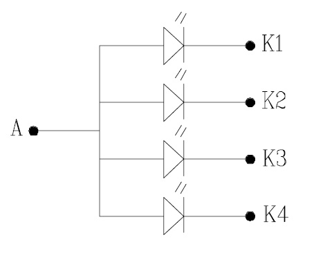
The backlight diodes are driven by the circuit shown in Figure 2.
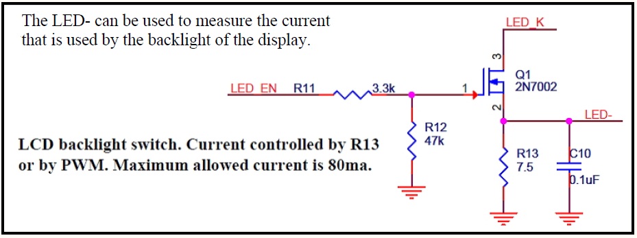
LED_K is connected to K1, K2, K3, K4 in Figure 2. The anode (A) in Figure 2 is connected to the supply voltage of the module (3.3V).
In a worst case scenario where the diodes have a forward voltage of 2.9V@20mA the voltage over R13 must be at least 3.3V – 2.9V = 0.4V. That means R13 needs to be at least 0.4V / 4 * 20 mA = 5 Ohm. The chosen resistor value of 7.5 Ohm will reduce the current to 0.4V / 7.5 Ohm = 53 mA in a worst case scenario. That means through each diode a current of 53 mA / 4 = 13.25 mA will flow. Because of the reduced current it is also possible to drive the backlight without PWM. The LED- signal can be used to measure the current that flows through the backlight diodes. LED_EN can be used to enable the backlight, which is by default off, either by using PWM or by driving this signal to VCC.