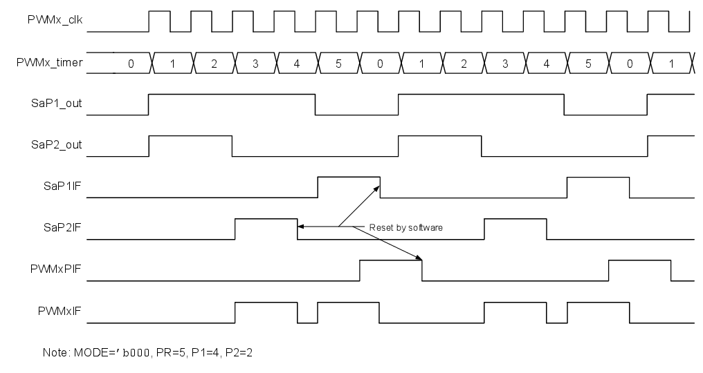
In Left Aligned mode the active part of the duty cycle is at the beginning of the
period. The outputs start active and stay active for the number of prescaled PWM clock
periods specified by the P1 and P2 parameter registers then go inactive for the
remainder of the period. Block and timing diagrams follow.
Figure 1. Left Aligned Block
Diagram
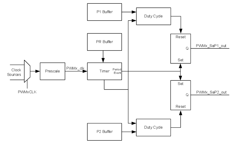
Figure 2. Left Aligned Timing
Diagram