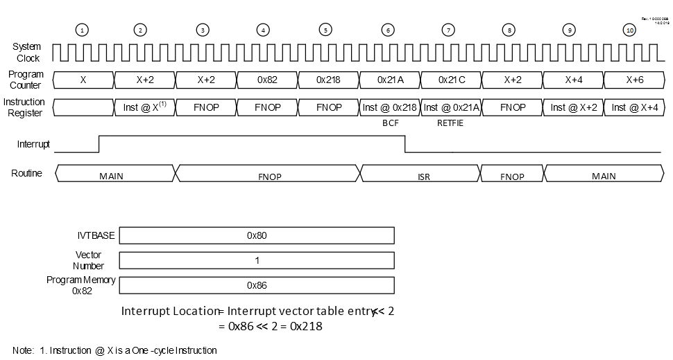
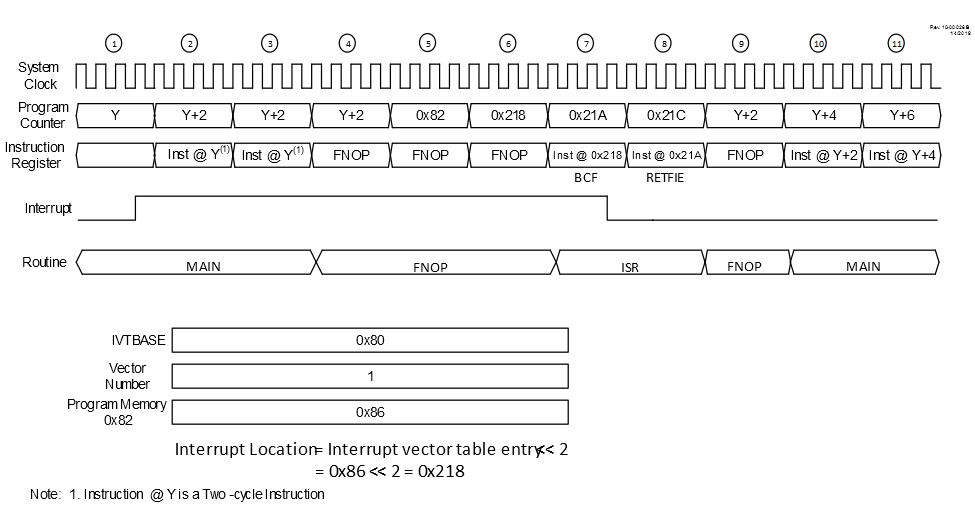
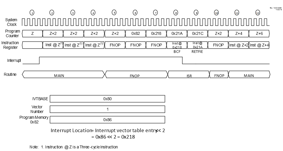
When MVECEN = 1, there is a fixed latency of three
instruction cycles between the completion of the instruction active when the interrupt
occurred, and the first instruction of the Interrupt Service Routine. Figure 1, Figure 2, and Figure 3 illustrate the sequence of events when a peripheral
interrupt is asserted, when the last executed instruction is one-cycle, two-cycle and
three-cycle, respectively.
After the Interrupt Flag Status bit is set, the current instruction completes
executing. In the first latency cycle, the contents of the PC, STATUS, WREG, BSR,
FSR0/1/2, PRODL/H and PCLATH/U registers are context saved and the IVTBASE + Vector
number is calculated. In the second latency cycle, the PC is loaded with the calculated
vector table address for the interrupt source and the starting address of the ISR is
fetched. In the third latency cycle, the PC is loaded with the ISR address. All the
latency cycles are executed as NOP instructions.
When MVECEN = 0, the interrupt controller requires two clock
cycles to vector to the ISR from the main routine. Note that as this mode requires
additional software to determine which interrupt source caused the interrupt, the actual
latency between the trigger and the beginning of the specific ISR for each individual
interrupt will be longer than two clock cycles and will vary, when not using vectored
interrupts.