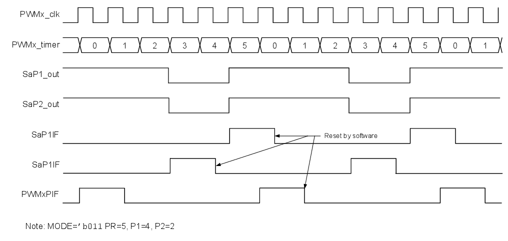
In Variable Alignment mode the active part of the duty cycle starts when the
parameter 1 value (P1) matches the timer and ends when the parameter 2 value (P2)
matches the timer. Both outputs are identical because both parameter values are used for
the same duty cycle. Block and timing diagrams follow.
Figure 1. Variable Alignment Block
Diagram
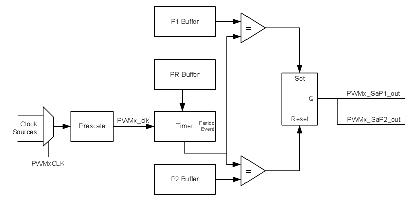
Figure 2. Variable Alignment Timing
Diagram