The CKP, CKE, and SMP bits control the relationship between the SCK clock
output, SDO output data changes, and SDI input data sampling. The bit functions are as
follows:
- CKP controls SCK output polarity
- CKE controls SDO output change relative to the SCK clock
- SMP controls SDI input sampling relative to the clock edges
The CKE bit, when set, inverts the low Idle state of the SCK output to a high Idle state.
The following figures illustrate the eight possible combinations of the CKP,
CKE, and SMP bit selections.
Important: All timing diagrams assume the LSBF bit is cleared.
Figure 1. Clocking Detail - Master Mode, CKE
= 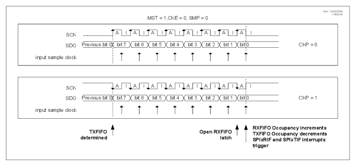
0, SMP = 0
Figure 2. Clocking Detail - Master Mode, CKE
= 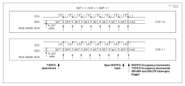
1, SMP = 1
Figure 3. Clocking Detail - Master Mode, CKE
= 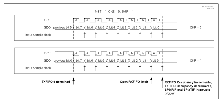
0, SMP = 1
Figure 4. Clocking Detail - Master Mode, CKE
=
1, SMP = 0
