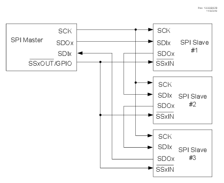
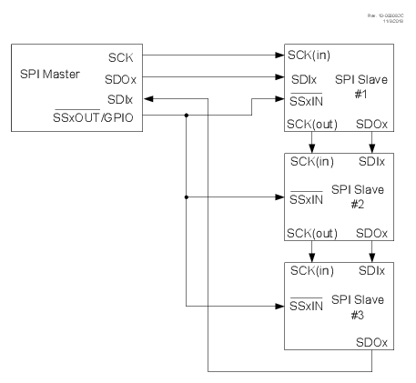
The SPI bus can be connected in a daisy-chain configuration. The first slave output is connected to the second slave input, the second slave output is connected to the third slave input, and so on. The final slave output is connected to the master input. Each slave sends out, during a second group of clock pulses, an exact copy of what was received during the first group of clock pulses. The whole chain acts as one large communication shift register. The daisy-chain feature only requires a single Slave Select line from the master device connected to all slave devices (alternately, the slave devices can be configured to ignore the Slave Select line by setting the SSET bit). In a typical daisy-chain configuration, the SCK signal from the master is connected to each of the slave device SCK inputs. However, the SCK input and output are separate signals selected by the PPS control. When the PPS selection is made to configure the SCK input and SCK output on separate pins then, the SCK output will follow the SCK input, allowing for SCK signals to be daisy-chained like the SDO/SDI signals.
The following two figures show block diagrams of a typical daisy-chain connection, and a daisy-chain connection with daisy-chained SPI clocks, respectively.