The pinout for the 6-pin aWire connector is shown in Figure 1
Note: Atmel AVR JTAGICE mkII units
with hardware revision 0 do NOT have aWire capabilities. For more information on which
hardware revision your unit is, see Hardware Revisions.
If your unit is revision 0, then aWire programming and debugging is not possible using this hardware. The JTAG interface (if available on your target device) does however provide the same functionality as aWire, although it uses I/O pins on the target device.
The pinout shown above is the recommended pinout for aWire, and will be supported natively by future aWire capable tools. The JTAGICE mkII requires that the 10-pin multicolored "squid" cable be used to map to this pinout.
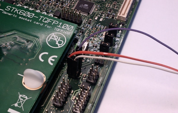
| JTAGICE mkII probe | Target pins | Squid cable colors | aWire pinout |
|---|---|---|---|
| Pin 1 (TCK) | Black | ||
| Pin 2 (GND) | GND | White | 6 |
| Pin 3 (TDO) | Grey | ||
| Pin 4 (VTref) | VTref | Purple | 2 |
| Pin 5 (TMS) | Blue | ||
| Pin 6 (nSRST) | Green | ||
| Pin 7 (Not connected) | Yellow | ||
| Pin 8 (nTRST) | Orange | ||
| Pin 9 (TDI) | aWire | Red | 1 |
| Pin 10 (GND) | Brown |