The algorithm for reading the Fuse and Lock bits is as follows (Please refer to Programming the Flash for details on Command loading):
- Step A: Load Command “0000 0100”.
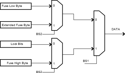
- Set OE to “0”, BS2 to “0” and BS1 to “0”. The status of the Fuse Low bits can now be read at DATA (“0” means programmed).
- Set OE to “0”, BS2 to “1” and BS1 to “1”. The status of the Fuse High bits can now be read at DATA (“0” means programmed).
- Set OE to “0”, BS2 to “1”, and BS1 to “0”. The status of the Extended Fuse bits can now be read at DATA (“0” means programmed).
- Set OE to “0”, BS2 to “0” and BS1 to “1”. The status of the Lock bits can now be read at DATA (“0” means programmed).
- Set OE to “1”.
Figure 1. Mapping Between BS1, BS2 and the
Fuse and Lock Bits During Read