The 8-bit Timer0 is a synchronous Timer. This means that it is clocked by the system clock, a prescaled system clock, or an external clock, which is synchronized with the system clock (see section Clock Options for more details about this). This timer is the least complex of the three. Only a few settings have to be made to get it running.
The following example will show how the Timer0 can be used to generate Timer
Overflow Interrupt. With every interrupt, pin PB5 on Port B will be toggled. To observe
this, the STK®600 Development Board or the ATmega328PB Xplained
Mini can be used. On STK600, PB5 has to be connected to an LED. The LED will blink with
a frequency (fLED) that is determined by the following formula: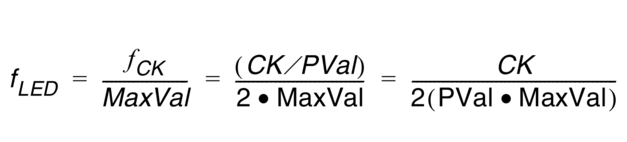
A system consisting of an 8-bit timer (MaxVal = 256) and a system clock of CK = 1 MHz, which is divided by a prescaler value of PVal = 1024, will cause the LED to blink with a frequency (fLED) of approximately 3.8Hz. The following initialization routine shows how to set up such a system:
init_Ex1:
	ldi r16,(1<<CS02)|(1<<CS00)
	out TCCR0B,r16 ; Timer clock = system clock / 1024
	ldi r16,1<<TOV0
	out TIFR0,r16 ; Clear TOV0/ Clear pending interrupts
	ldi r16,1<<TOIE0
	sts TIMSK0,r16 ; Enable Timer/Counter0 Overflow Interrupt
	ret
The corresponding C code looks like
this:
void init_Ex1(void)
{
	/* Timer clock = I/O clock / 1024 */
	TCCR0B = (1<<CS02)|(1<<CS00);
	/* Clear overflow flag */
	TIFR0  = 1<<TOV0;
	/* Enable Overflow Interrupt */
	TIMSK0 = 1<<TOIE0;
}
In the next step, the interrupt service routine has to be implemented. This
routine will be executed with every timer overflow. The purpose of the routine in this
example is to toggle
PB5.
ISR_TOV0:
	push r16
	in r16,SREG
	push r16
	call TOGGLEPIN
	pop r16
	out SREG,r16
	pop r16
	reti
TOGGLEPIN:
	sbic portb,PORTB5
	rjmp CLEARPIN
	nop
	sbi portb,PORTB5
	jmp RET1
CLEARPIN:
	cbi portb,PORTB5
RET1:
	ret
The corresponding C
code:
ISR (TIMER0_OVF_vect)
{
	/* Toggle a pin on timer overflow */
	PORTB  ^= (1 << USER_LED);
}