There are 17 white LEDs arranged in a 4x4 matrix on the QT3 Xplained Pro extension board which can be used to visualize a touch in the QTouch sensor. All LEDs on the boards must be driven by the I/O of the target controller on an MCU board.
Figure 1. LED Connection Diagram
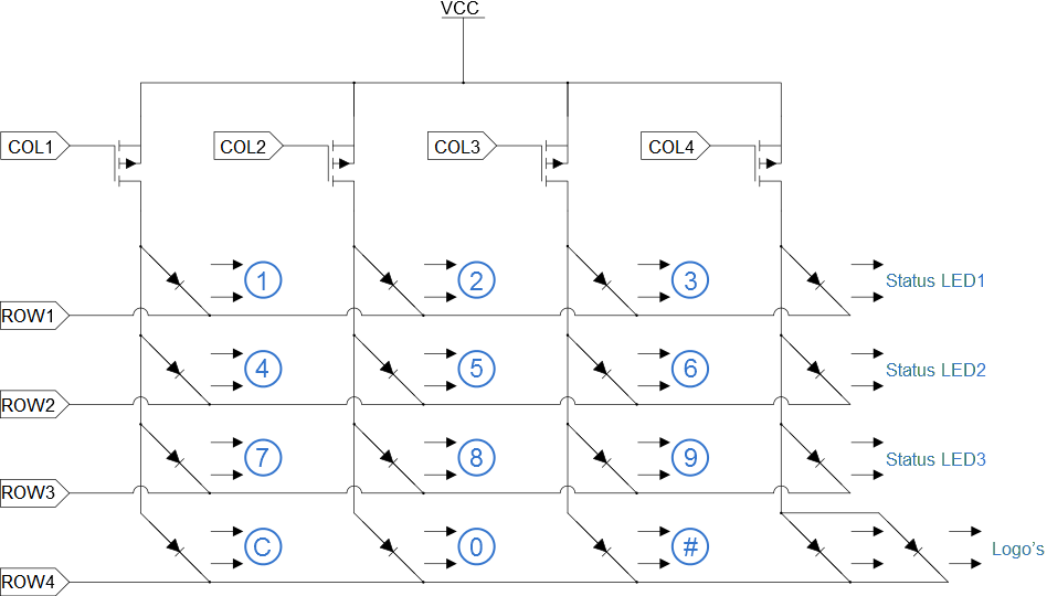
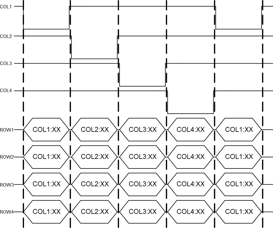
The LEDs must be driven with multiplexing techniques. Drive only one colum at the time by pulling the respective COL line low and keep the other COL lines high. The columns are driven with a FET gate and can therefore deliver current to all the LEDs in that column. The LED rows are connected directly to the MCU and can only sink one LED at the time. See Figure 2 for an illustration of the driving waveform.
Figure 2. LED Driving Waveform
| Pin on EXT1 | Function | Description |
|---|---|---|
| 15 | LED COL1 | Column 1, driving LEDs backlight for keypad: "1", "4", "7", and "C" |
| 16 | LED COL2 | Column 2, driving LEDs backlight for keypad: "2", "5", "8", and "0" |
| 17 | LED COL3 | Column 3, driving LEDs backlight for keypad: "3", "6", "9", and "#" |
| 18 | LED COL4 | Column 4, driving status LED1, 2, and 3, and Logo's backlight |
| Pin on EXT2 | Function | Description |
|---|---|---|
| 7 | LED ROW1 | Row 1, driving LEDs backlight for keypad: "1", "2", "3", and one status LED1 |
| 8 | LED ROW2 | Row 2, driving LEDs backlight for keypad: "4", "5", "6", and one status LED2 |
| 9 | LED ROW3 | Row 3, driving LEDs backlight for keypad: "7", "8", "9", and one status LED3 |
| 10 | LED ROW4 | Row 4, driving LEDs backlight for keypad: "C", "0", "#", and Logo's |