The Flash memory can be divided into three sections: Boot Loader (BOOT), Application
Code (APPCODE) and Application Data (APPDATA). The main difference between these
sections are access privileges:
- The code in the BOOT section can write to APPCODE and APPDATA
- The code in APPCODE can write to APPDATA
- The code in APPDATA cannot write to Flash or EEPROM
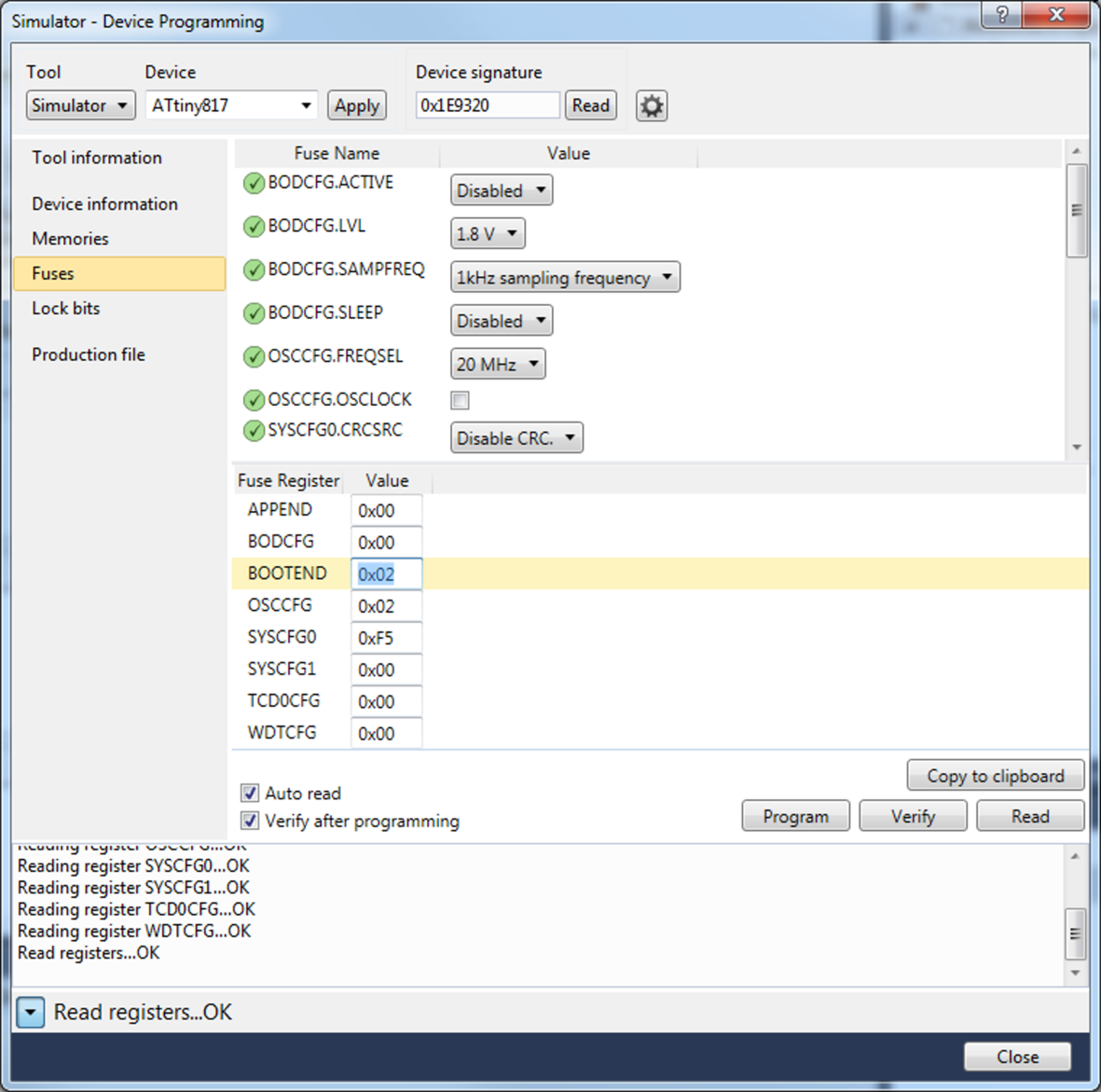
Figure 1 shows how the Flash sections are ordered in the Flash.
Figure 1. Flash Sections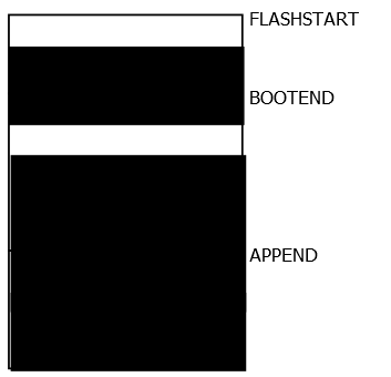
FLASHSTART is at 0x0000 when accessed as program
memory, and mapped with the following offsets when accessed via data memory:
- megaAVR 0-series: 0x4000
- tinyAVR 0- and 1-series: 0x8000
uint8_t *flash_pointer = (uint8_t *) 0x100 + MAPPED_PROGMEM_START;
The size of the Flash sections can be configured through the BOOTEND and APPEND fuses in steps of 256 bytes (128 words). The following table shows how these fuses configure the sections.
| BOOTEND | APPEND | BOOT Section | APPCODE Section | APPDATA Section |
|---|---|---|---|---|
| 0 | 0 | 0 to FLASHEND | - | - |
| > 0 | 0 | 0 to 256*BOOTEND | 256*BOOTEND to FLASHEND | - |
| > 0 | == BOOTEND | 0 to 256*BOOTEND | - | 256*BOOTEND to FLASHEND |
| > 0 | > BOOTEND | 0 to 256*BOOTEND | 256*BOOTEND to 256*APPEND | 256*APPEND to FLASHEND |
A good way of making sure these fuses are set up as expected on a device is
to use the FUSES macro in the bootloader code project. It can be found
in fuse.h, which is included by
io.h:
#include <avr/io.h>

FUSES = {
	.OSCCFG = FREQSEL_20MHZ_gc,
	.SYSCFG0 = CRCSRC_NOCRC_gc | RSTPINCFG_UPDI_gc,
	.SYSCFG1 = SUT_64MS_gc,
	.APPEND = 0x00, // Application data section disabled
	.BOOTEND = 0x02 // Boot section size = 0x02 * 256 bytes = 512 bytes
};
This
will compile the fuse settings into the elf-file for the bootloader, and if this is used
to program the device instead of the hex-file, the fuse settings will be programmed at
the same time as the Flash.Note: All fuse bytes in the struct must be
configured, not only BOOTEND and APPEND. This is because an omitted fuse byte will be
set to 0x00 and may cause an unwanted configuration.
The device fuses can also be configured directly from Atmel® Studio 7.0, using Device Programming (Ctrl+Shift+P) - Fuses, as shown in Figure 2.
Figure 2. Configure BOOTEND and APPEND fuses, Atmel Studio 7.0