In this section, CCL and SPI will be used to build a Manchester encoder and to transmit a Manchester-encoded signal. This requires very few CPU cycles to load the input data to SPI, and the rest of the work is performed by the CCL and SPI modules.
The Manchester code is a type of line code that has constant DC component.
There are two versions of the Manchester code; this document refers to the version
defined in the IEEE 802.3 standard. The Manchester code combines data and clock into a
single signal, where one clock cycle is a Manchester-bit period. A transition always
occurs in the middle of the bit period. DATA = 0 is represented by a
falling edge (high-to-low transition) in the middle of the bit period, and DATA =
1 is represented by a rising edge (low-to-high transition) in the
middle of the bit period. An example is shown below.
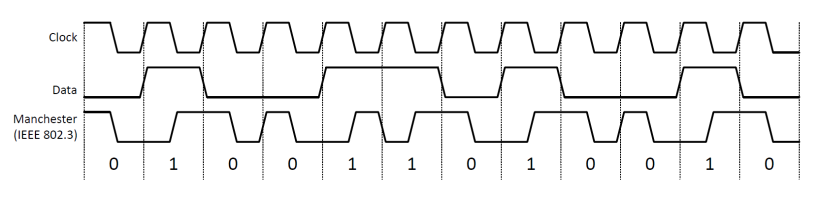
One way to obtain the Manchester encoded data is to use the XOR function between clock and data. In the current example, the SPI module is used to generate clock and data signals for the encoder.
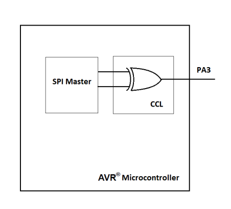
The SPI module should be configured as master to generate signals on the outputs.
void SPI0_init()
{

	SPI0.CTRLA = SPI_ENABLE_bm
	             | SPI_MASTER_bm;
}
LUT0 is then configured to use SPI MOSI and SPI SCK signals as inputs. The unused LUT0 input will be masked.
CCL.LUT0CTRLB = CCL_INSEL0_MASK_gc | CCL_INSEL1_SPI0_gc;

CCL.LUT0CTRLC = CCL_INSEL2_SPI0_gc;
To create a logic XOR function between LUT0_IN[1] and LUT0_IN[2], the value of the truth table should be 0x14.
CCL.TRUTH0 = 0x14;To complete the setup and enable the LUT0 output on the LUT0OUT pin (PA3), CCL and LUT0 need to be enabled.
CCL.LUT0CTRLA = CCL_ENABLE_bm | CCL_OUTEN_bm;

CCL.CTRLA = CCL_ENABLE_bm;
