| Standard Operating Conditions (unless otherwise stated) | |||||||
|---|---|---|---|---|---|---|---|
| Param. No. | Sym. | Characteristic | Min. | Typ.† | Max. | Units | Conditions |
| Supply Voltage | |||||||
| D002 | VDD |
1.8 |
— |
5.5 |
V |
||
| RAM Data Retention(1) | |||||||
| D003 | VDR | 1.7 |
— |
— |
V |
Device in SLEEP mode |
|
| Power-on Reset Release Voltage(2) | |||||||
| D004 | VPOR |
— |
1.6 |
— |
V |
BOR or LPBOR disabled(3) | |
| Power-on Reset Rearm Voltage(2) | |||||||
| D005 | VPORR |
— |
1.25 |
— |
V |
BOR or LPBOR disabled(3) | |
| VDD Rise Rate to ensure internal Power-on Reset signal(2) | |||||||
| D006 | SVDD | 0.05 |
— |
— |
V/ms | BOR or LPBOR disabled(3) | |
|
Data in “Typ.” column is at 3.0V, 25°C unless otherwise stated. These parameters are for design guidance only and are not tested. Note:
|
|||||||
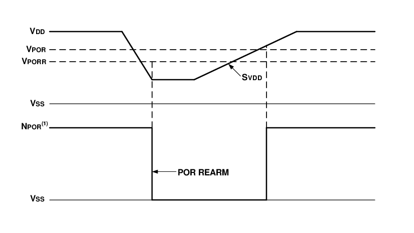
Figure 1. POR and POR Rearm with Slow Rising
VDD
Note:
- 1.When NPOR is low, the device is held in Reset.
- 2.TPOR 1 μs typical.
- 3.TVLOW 2.7 μs typical.