The Timer2 module is a 8-bit timer that incorporates the following features:
- 8-Bit Timer and Period Registers
- Readable and Writable
- Software Programmable Prescaler (1:1 to 1:128)
- Software Programmable Postscaler (1:1 to 1:16)
- Interrupt on T2TMR Match with T2PR
- One-Shot Operation
- Full Asynchronous Operation
- Includes Hardware Limit Timer (HLT)
- Alternate Clock Sources
- External Timer Reset Signal Sources
- Configurable Timer Reset Operation
See Figure 1 for a block diagram of Timer2. See table below for the clock source selections.
Important: References to module Timer2 apply to all the
even numbered timers on this device. (Timer2, Timer4, etc.)
Figure 1. Timer2 with Hardware Limit Timer (HLT) Block Diagram
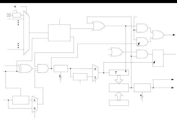
Note:
- 1.Signal to the CCP to trigger the PWM pulse.
- 2.See TxRST for external Reset sources.
| CS<3:0> | Clock Source | ||
|---|---|---|---|
| Timer2 | Timer4 | Timer6 | |
| 1111-1001 | Reserved | Reserved | Reserved |
| 1000 | ZCD_OUT | ZCD_OUT | ZCD_OUT |
| 0111 | CLKREF_OUT | CLKREF_OUT | CLKREF_OUT |
| 0110 | SOSC | SOSC | SOSC |
| 0101 | MFINTOSC (31 kHz) | MFINTOSC (31 kHz) | MFINTOSC (31 kHz) |
| 0100 | LFINTOSC | LFINTOSC | LFINTOSC |
| 0011 | HFINTOSC | HFINTOSC | HFINTOSC |
| 0010 | Fosc | Fosc | Fosc |
| 0001 | Fosc/4 | Fosc/4 | Fosc/4 |
| 0000 | Pin selected by T2INPPS | Pin selected by T4INPPS | Pin selected by T6INPPS |