For debuggers and/or programmers that support the Cortex Debug Connector (10-pin) interface the signals should be connected as shown in Figure 1 with details described in Table 1.
Figure 1. Cortex Debug Connector
(10-pin)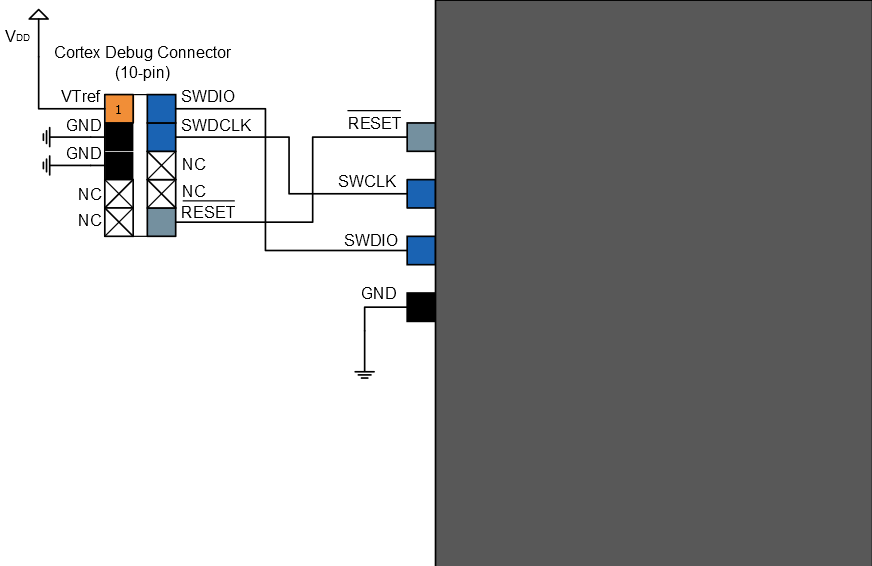
| Header Signal Name | Description |
|---|---|
| SWDCLK | Serial wire clock pin |
| SWDIO | Serial wire bidirectional data pin |
| RESET | Target device reset pin, active low |
| VTref | Target voltage sense, should be connected to the device VDD |
| GND | Ground |