In I2C Sm, Fm, and Fm+ mode, the Master clock (SCL) frequency is determined as described in this section:
The low (TLOW) and high (THIGH) times are determined by the Baud Rate register (BAUD), while the rise (TRISE) and fall (TFALL) times are determined by the bus topology. Because of the wired-AND logic of the bus, TFALL will be considered as part of TLOW. Likewise, TRISE will be in a state between TLOW and THIGH until a high state has been detected.
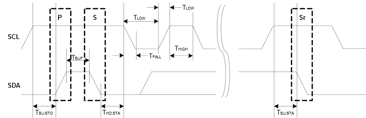
- TLOW – Low period of SCL clock
- TSU;STO – Set-up time for stop condition
- TBUF – Bus free time between stop and start conditions
- THD;STA – Hold time (repeated) start condition
- TSU;STA – Set-up time for repeated start condition
- THIGH is timed using the SCL high time count from BAUD.BAUD
- TRISE is determined by the bus impedance; for internal pull-ups. Refer to Electrical Characteristics.
- TFALL is determined by the open-drain current limit and bus impedance; can typically be regarded as zero. Refer to Electrical Characteristics for details.
The SCL frequency is given by:
When BAUD.BAUDLOW is zero, the BAUD.BAUD value is used to time both SCL high and SCL low. In this case the following formula will give the SCL frequency:
When BAUD.BAUDLOW is non-zero, the following formula determines the SCL frequency:
The following formulas can determine the SCL TLOW and THIGH times: