| Symbol | Parameter | Conditions | Min. | Typ. | Max. | Units | |
|---|---|---|---|---|---|---|---|
| tSCK | SCK period | Master | Reception | 2*(tMIS+tSLAVE_OUT) (3) | - | - | ns |
| Master | Transmission | 2*(tMOV+tSLAVE_IN) (4) | - | - | |||
| tSCKW | SCK high/low width | Master | - | 0.5*tSCK | - | ns | |
| tSCKR | SCK rise time (2) | Master | - | 0.25*tSCK | - | ns | |
| tSCKF | SCK fall time (2) | Master | - | 0.25*tSCK | - | ns | |
| tMIS | MISO setup to SCK | Master, VDD>4.5V | 50.7 | - | - | ns | |
| Master, VDD>2.7V | 60.6 | - | - | ||||
| tMIH | MISO hold after SCK | Master, VDD>4.5V | 0 | - | - | ns | |
| Master, VDD>2.7V | 0 | - | - | ||||
| tMOV | MOSI output valid SCK | Master, VDD>4.5V | - | - | 17.1 | ns | |
| Master, VDD>2.7V | - | - | 23.6 | ||||
| tMOH | MOSI hold after SCK | Master, VDD>4.5V | 2.5 | - | - | ns | |
| Master, VDD>2.7V | 2.5 | - | - | ||||
| tSSCK | Slave SCK Period | Slave | Reception | 2*(tSIS+tMASTER_OUT) (5) | - | - | ns |
| Slave | Transmission | 2*(tSOV+tMASTER_IN) (6) | - | - | |||
| tSSCKW | SCK high/low width | Slave | - | 0.5*tSSCK | - | ns | |
| tSSCKR | SCK rise time (2) | Slave | - | 0.25*tSSCK | - | ns | |
| tSSCKF | SCK fall time (2) | Slave | - | 0.25*tSSCK | - | ns | |
| tSIS | MOSI setup to SCK | Slave, VDD>4.5V | 13.6 | - | - | ns | |
| Slave, VDD>2.7V | 14.1 | - | - | ||||
| tSIH | MOSI hold after SCK | Slave, VDD>4.5V | 0 | - | - | ns | |
| Slave, VDD>2.7V | 0 | - | - | ||||
| tSSS | SS setup to SCK | Slave | PRELOADEN=1 | tSOSS+tEXT_MIS+2*tAPBC (8) (9) | - | - | ns |
| PRELOADEN=0 | tSOSS+tEXT_MIS (8) | - | - | ||||
| tSSH | SS hold after SCK | Slave | 0.5*tSSCK | - | - | ns | |
| tSOV | MISO output valid SCK | Slave, VDD>4.5V | - | - | 45 | ns | |
| Slave, VDD>2.7V | - | - | 55.1 | ||||
| tSOH | MISO hold after SCK | Slave, VDD>4.5V | 11.9 | - | - | ns | |
| Slave, VDD>2.7V | 11.9 | - | - | ||||
| tSOSS | MISO setup after SS low | Slave, VDD>4.5V | - | - | 41 | ns | |
| Slave, VDD>2.7V | - | - | 50.7 | ||||
| tSOSH | MISO hold after SS high | Slave, VDD>4.5V | 11.1 | - | - | ns | |
| Slave, VDD>2.7V | 11.1 | - | - | ||||
- These values are based on simulation. These values are not covered by test limits in production.
- See I/O pin characteristics.
- Where tSLAVE_OUT is the slave external device output response time, generally tEXT_SOV+tLINE_DELAY (7).
- Where tSLAVE_IN is the slave external device input constraint, generally tEXT_SIS+tLINE_DELAY (7).
- Where tMASTER_OUT is the master external device output response time, generally tEXT_MOV+tLINE_DELAY (7).
- Where tMASTER_IN is the master external device input constraint, generally tEXT_MIS+tLINE_DELAY (7).
- tLINE_DELAY is the transmission line time delay.
- tEXT_MIS is the input constraint for the master external device.
- tAPBC is the APB period for SERCOM.
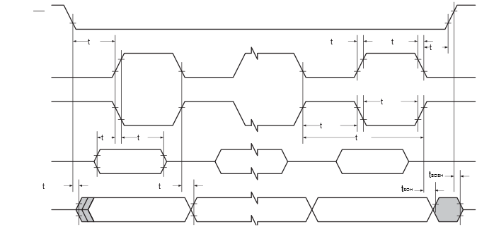
Figure 1. SPI Timing Requirements in Master
Mode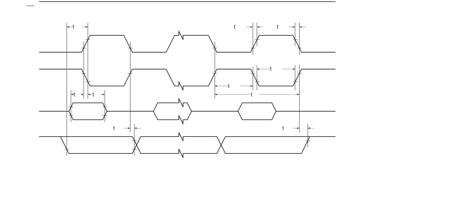
Figure 2. SPI Timing Requirements in Slave
Mode