Since
ADC generates digital
output,
it is
not possible to provide continuous output
values.
The perfect ADC performs
the
process of quantization
during
conversion. This results in a staircase transfer function where each step represents one
LSB.
Figure 1. Perfect ADC in Single-ended
Mode
(Unadjusted Quantization)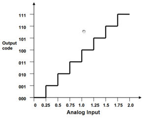
Consider
an
example with VREF = 2V and Resolution = 3-bits, the step size is 250mV (1
LSB). The input analog voltage
ranges
from 0V to 250mV will be assigned the digital output code 000 and the input analog
voltage range from 251mV to 500mV will be assigned the digital code 001 and so on. This
is depicted in Figure 1
which shows the transfer function of a perfect 3-bit ADC operating in
single ended mode. Figure 2, shows the transfer function of a perfect 3-bit ADC
operating in differential mode.
Figure 2. Perfect ADC in Differential
Mode
(Unadjusted Quantization)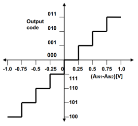
Note: In
the above
example,
the differential analog input voltage can vary from -1V to +1V and the MSB acts as
sign bit.
From the Figure 1, it is obvious that an input voltage of 0V produces an
output code 000. At the same time, an input voltage of 250mV also produces the same
output code 000. This explains the quantization error due to the process of
quantization. As the input voltage rises from 0V, the quantization error also rises from
0LSB and reaches a maximum quantization error of 1LSB at 250mV.
Again,
the quantization error increases from 0 to 1LSB as the input rises from 250mV to 500mV.
This maximum quantization error of 1LSB can be reduced to ±0.5LSB by shifting the
transfer function towards left through 0.5LSB.
Figure 3. Perfect ADC in Single-ended
Mode
(Adjusted Quantization)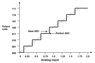
Figure 3 depicts the quantization adjusted perfect transfer
function together with the ideal transfer function. As seen on the figure, the perfect
ADC equals the ideal ADC on the exact midpoint of every step. This means that the
perfect ADC essentially rounds input values to the nearest output step value.
Similarly,
Figure 4 is for differential ADC.
Figure 4. Perfect ADC in Differential
Mode
(Adjusted Quantization)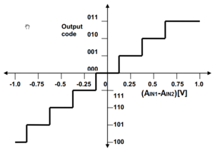
The Quantization error is only considered in a model such as a Perfect ADC. However, in real-time the actual ADC has several other errors apart from quantization error. These errors are explained in the upcoming sections.