One of the most important characteristics of the TCA when compared to other timers, such as TCB, is the versatility and precision of the PWM generation. The user can choose from various configurations according to the complexity of the application. The TCA can be configured in both Single-Slope and Dual-Slope PWM Generation modes, which permit the trade-off between a constant phase (Correct Phase PWM) and a higher maximum operation frequency (Fast PWM). In addition, the TCA has a buffering scheme that ensures a glitch-free PWM.
Both TCA and TCB can be used to generate a PWM signal with a high maximum operation frequency, but only the TCA can be used in critical applications due to its dual-slope PWM capabilities given by its selectable direction. Dual-slope PWM does not modify the pulse center position when the duty cycle is changed. Thus, the phase is always constant.
The buffering scheme contains a buffer for each Compare register as well as for the Period register. The use of this buffers is essential in critical applications where an unexpected long pulse can lead to a short circuit. Moreover, the presence of these buffers can prevent the loss of synchronisation between two peripherals that use the same timer but different compare channels. However, given the fact that the Period and Compare registers can be updated directly, the buffering scheme can be avoided by the user. The following wave forms illustrate the difference between buffered and unbuffered operations.
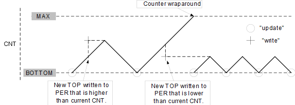
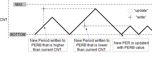
If the user changes the Period register directly, it is possible that the timer has already passed the new threshold, so it will continue counting to the maximum value. That will cause an unusually long pulse that can cause further problems. Also, if two or more compare channels are used and one of them is updated, the sync between the triggers may be lost. To prevent all these possible problems the use of the buffering scheme is required. The buffers hold the new value and transfer it to the Compare or the Period register accordingly when the timer is updated. With all values changed at the same time, the problems mentioned disappear.
Below is an example of how to set a TCA instance to generate a 1 kHz PWM signal with 50% duty cycle using the buffering scheme described above.
- 1.The TCA corresponding register in
Port Multiplexer can be set to route the module outputs to different ports, in this
case, Port A is chosen, which is also the default
port.
PORTMUX.TCAROUTEA = PORTMUX_TCA0_PORTA_gc;
Figure 3. PORTMUX Control for TCA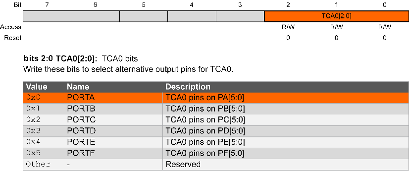
- 2.The CTRLB register contains the
Enable bits of the compare channels and the bit field that determines the Waveform
Generation mode. In this example, channel 0 is used together with a Dual-Slope PWM
mode.
TCA0.SINGLE.CTRLB = TCA_SINGLE_CMP0EN_bm
                        | TCA_SINGLE_WGMODE_DSBOTTOM_gc;
Figure 4. CTRLB Register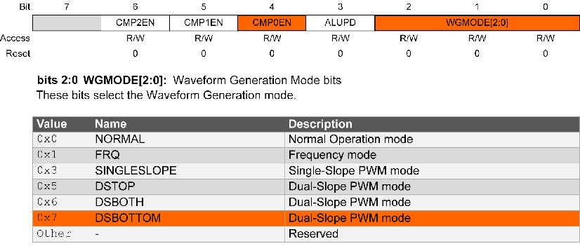
- 3.The CNTEI bit of the EVCTRL register
is set to ‘
0’ in order to set the timer to count clock ticks instead of events. It is worth mentioning that this is the default value of the CNTEI bit.TCA0.SINGLE.EVCTRL &= ~(TCA_SINGLE_CNTEI_bm);
Figure 5. EVCTRL Register
- 4.PERBUF is the buffer of the Period
register. It is used to set the frequency of the PWM signal using the following
formula.
TCA0.SINGLE.PERBUF = 0x01A0;
- 5.Also, the Compare register is updated using its buffer in order to set the duty
cycle. The value in the Compare register is half of the one in the Period register
because a 50% duty cycle is
desired.
TCA0.SINGLE.CMP0BUF = 0x00D0; - 6.The prescaler can be set to 4 by
changing the CLKSEL bit field in the CTRLA register. To start the counter, the user
has to set the Enable bit in the same
register.
TCA0.SINGLE.CTRLA = TCA_SINGLE_CLKSEL_DIV4_gc
                           | TCA_SINGLE_ENABLE_bm;
Figure 6. CTRLA Register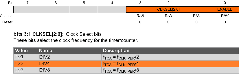
- 7.Then, the Port A Pin 0 (PA0) is set
as output by writing a ‘
1’ to the corresponding bit in the Direction register of the port.PORTA.DIR |= PIN0_bm;
