A basic use case of the timer is to set it to trigger an interrupt every time it is updated. This mode is useful if a piece of code must be executed repeatedly every few milliseconds. The user must enable the interrupts and set an Interrupt Service Routine (ISR), which will contain the appropriate code. A basic example containing the initialization and an ISR is provided below. The program will toggle a pin every 250 ms using TCA's periodic interrupts. A pin must be configured as an output by setting the corresponding bit of the Direction register before the initialization of the timer as described below. In this case, Port A pin 0 (PA0) was chosen.
- 1.Setting the corresponding bit in the
Interrupt Control register enables the overflow interrupt of
TCA.
TCA0.SINGLE.INTCTRL = TCA_SINGLE_OVF_bm;
Figure 1. Interrupt Control Register
- 2.In this mode, no waveform must be
generated, so the Waveform Generation bit field in the CTRLB register must be
configured
accordingly.
TCA0.SINGLE.CTRLB = TCA_SINGLE_WGMODE_NORMAL_gc;
Figure 2. CTRLB Register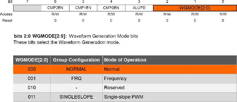
- 3.Since the timer may count clock
ticks, not events, the CNTEI bit of the EVCTRL register must be set to
‘
0’. It is worth mentioning that this is the default value of the CNTEI bit.TCA0.SINGLE.EVCTRL &= ~(TCA_SINGLE_CNTEI_bm);
Figure 3. EVCTRL Register
- 4.The value written in the Period
register represents the number of clock ticks between the moment when the timer
starts and the moment when the first interrupt is triggered; and also the number of
clock ticks between two consecutive interrupts. It can be deduced from the following
equation. Note: The value written to the Period register will be one less than the desired count, because the counting starts from ‘
0’.Note: The Period register is 16 bits wide, thus the longest achievable interrupt period with no TCA prescaler is listed below.TCA0.SINGLE.PER = 0x0CB6;
- 5.From the CTRLA register, the
prescaler is set to ‘256’. To start the counter, the user must set the Enable bit in
the same
register.
TCA0.SINGLE.CTRLA = TCA_SINGLE_CLKSEL_DIV256_gc
                           | TCA_SINGLE_ENABLE_bm;
Figure 4. Control A Register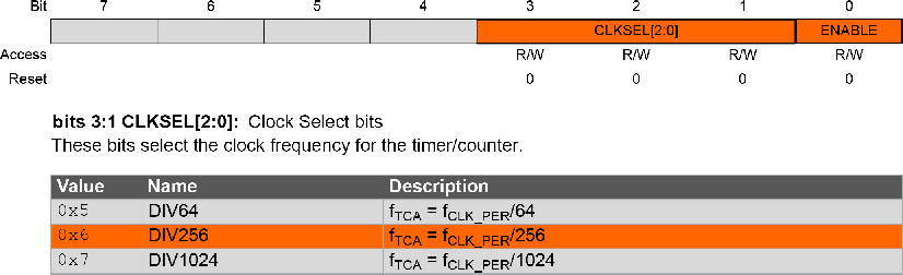
- 6.After the timer is fully configured,
the
sei();macro enables the global interrupts. The peripherals need to always be configured when the global interrupts are disabled in order to avoid problems.In the ISR, the output pin is toggled by setting the corresponding bit in the Input register of the port. Also, the Overflow Interrupt flag is cleared.Tip: Interrupt flags have to be cleared in software by writing ‘1’ at the respective bit location.ISR(TCA0_OVF_vect) { PORTA.OUTTGL = PIN0_bm; TCA0.SINGLE.INTFLAGS = TCA_SINGLE_OVF_bm; }Figure 5. INTCTRL Register
An interrupt request is generated when the corresponding interrupt source is enabled, and the Interrupt flag is set. As soon as the flag is set, the microcontroller will start executing the code from the ISR written by the user. The interrupt request remains active until the Interrupt flag is cleared. The parameter of the ISR is the interrupt vector. Therefore, the user can specify what interrupt source the ISR corresponds to. A list of the TCA interrupt vectors is provided below. When programming, it is useful to use the autocomplete function of the IDE to identify the desired interrupt vector.Figure 6. Available Interrupt Vectors and Sources in Normal Mode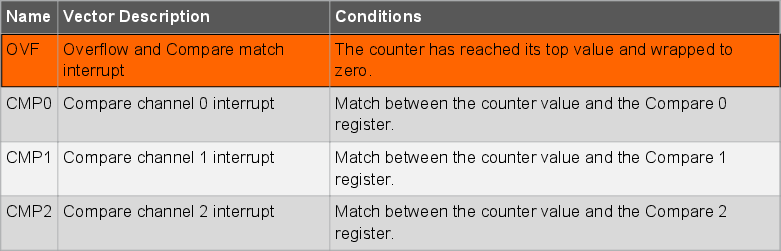
- 7.The Port A pin 0 (PA0) is set as
output by writing a ‘
1’ to the corresponding bit in the Direction register of the port. This GPIO is configured only to obtain a visible output, but it has nothing to do with the TCA instance itself in this mode.PORTA.DIR |= PIN0_bm;

Tip: The full code example is
also available in Appendix section.