All transmission and reception of serial data on the UPDI is achieved using the UPDI frames presented in Figure 1. Communication is initiated from the master (debugger) side, and every transmission must start with a SYNCH character upon which the UPDI can recover the transmission baud rate, and store this setting for the coming data. The baud rate set by the SYNCH character will be used for both reception and transmission for the instruction byte received after the SYNCH. See UPDI Instruction Set for details on when the next SYNCH character is expected in the instruction stream.
There is no writable baud rate register in the UPDI, so the baud rate sampled
from the SYNCH character is used for data recovery by sampling the start bit, and do a
majority voting on the middle samples. This process is repeated for all bits in the
frame, including the parity bit and two stop bits. The baud generator uses 16 samples,
and the majority voting is done on sample 7,8 and 9.
Figure 1. UPDI UART Start Bit and Data/Parity/Stop bit sampling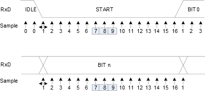
The transmission Baud Rate must be set up in relation to the selected
UPDI clock, which can be adjusted by UPDICLKSEL in UPDI.ASI_CTRLA. See Table 1 for recommended maximum and minimum baud rate
settings.
| UPDICLKSEL[1:0] | MAX Recommended Baud Rate | MIN Recommended Baud Rate |
|---|---|---|
| 0x1 (16MHz) | 0.9Mbps | 0.300kbps |
| 0x2 (8MHz) | 450kbps | 0.150kbps |
| 0x3 (4MHz) - Default | 225kbps | 0.075kbps |
The UPDI baud rate generator utilizes fractional baud counting to minimize
the transmission error. With the fixed frame format used by the UPDI, the maximum and
recommended receiver transmission error limits can be seen in the following table:
| Data + parity bits | Rslow | Rfast | Max Total Error (%) | Recommended max RX error (%) |
|---|---|---|---|---|
| 9 | 96.39 | 104.76 | +4.76 / -3.61 | +1.5 / -1.5 |