Max continuous current: +/-3A.
Max input voltage: 9V.
| Frequency [MHz] | Active mode [mA] | Idle mode [mA] | Power save [µA] |
|---|---|---|---|
| 1 | 1.00 | 0.38 | 30 |
Application current consumption is dependant on the firmware, and if communications are active as the ATmega16HVA has no hardware UART. AVR455 showed a typical current consumption of 160uA for SB201-1 in a 1-cell application.
Schematics
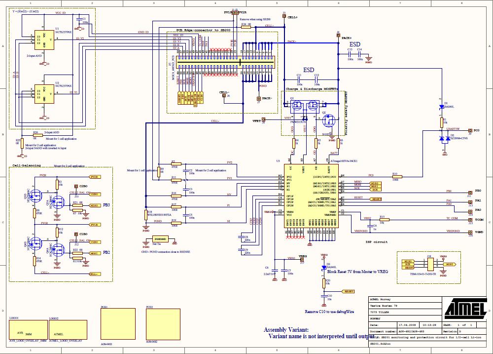
The schematics for SB201-1 and SB201-2 are provided in the .zip-file that can be downloaded from Atmel AVR Application notes. A small version of the common schematic is provided here.
Component placement
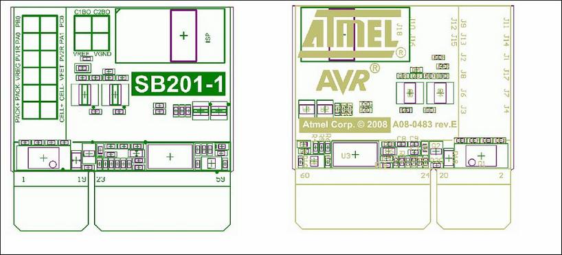
Component placement for SB201-1 and SB201-2 are provided in the .zip-file that can be downloaded from Atmel AVR Application notes. A small version of SB201-1 is shown here.
Bill of Materials
The BOM is provided in the .zip file that can be downloaded from Atmel AVR Application notes. The difference between SB201-1 and SB201-2 is that the SB201-2 provides cell balancing circuitry. Otherwise the SB201-1 has a 0 Ω resistor connecting PV2 and PV1, and the board identification has a different resistor mounting.