This use case demonstrates how to send a string to the PC and show it in the terminal. There are plenty of options available for UART to USB convertors (such as MCP2200) and PC serial terminal software (such as Data Visualizer in Atmel Studio). The USART will be configured for Asynchronous mode and only the TX pin will be used.
This use case follows the steps:
- Set the baud rate
- Enable the Transmitter (TX)
- Configure the pins
How to Configure the Baud Rate
The baud rate shows how many bits are sent per second. The higher the baud rate, the faster the communication. Common baud rates are: 1200, 2400, 4800, 9600, 19200, 38400, 57600 and 115200, with 9600 being the most commonly used one.
On the megaAVR 0-series, the maximum baud will be limited to 1/8 * (Maximum USART clock) in Async mode and 1/2 * (Maximum USART clock) in Sync mode. To set the baud rate, write to USARTn.BAUD register:
USART0.BAUD = (uint16_t)USART0_BAUD_RATE(9600);
Notice the use of the USART0_BAUD_RATE macro to compute the
register’s value from the baud value. This macro must be defined based on the formula in
the image below. This formula depends on the settings of the USART, so it might not be
the same in other modes.
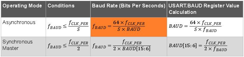
S is the number of samples per bit. In Asynchronous operating mode, it is 16 (NORMAL mode) or 8 (CLK2X mode). For Synchronous operating mode, S equals 2.
This is how the USART0_BAUD_RATE macro is defined. It uses
F_CPU because the USART clock machetes the CPU clock.
#define F_CPU 3333333
#define USART0_BAUD_RATE(BAUD_RATE) ((float)(F_CPU * 64 / (16 * (float)BAUD_RATE)) + 0.5)
How to Enable the Transmitter and Send Data
Depending on the application needs, the user may choose to only enable the receiver or the transmitter of the USART module. Since in this use case only the microcontroller sends messages, only the transmitter needs to be enabled.
USART0.CTRLB |= USART_TXEN_bm;
Before sending data, the user needs to check if the previous transmission is completed by checking the USARTn.STATUS register. The following code example waits until the transmit DATA register is empty and then writes a character to the USARTn.TXDATA register:
void USART0_sendChar(char c)
{
    while (!(USART0.STATUS & USART_DREIF_bm))
    {
        ;
    }
    USART0.TXDATAL = c;
}
The Send register is nine bits long. Therefore, it was split into two parts: the lower part that holds the first eight bits, called TXDATAL, and the higher part that holds the remaining one bit, called TXDATAH. TXDATAH is used only when the USART is configured to use nine data bits. When used, this ninth bit must be written before writing to USARTn.TXDATAL, except if CHSIZE in USARTn.CTRLC is set to “9-bit - Low byte first”, where USARTn.TXDATAL should be written first.
How to Configure Pins
The TX pin must be configured as output. By default, each peripheral has some associated pin positions. The pins can be found in the device-specific data sheet, in the Multiplexed Signals section. Each USART has two sets of pin positions. The default and alternate pin positions for USART0 are shown below.
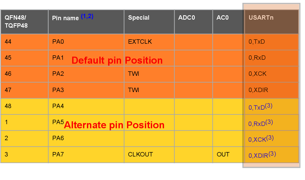
For this use case, the default USART0 pin position is used; this is PA0 to PA3. The following code sets the TX pin direction to output.
PORTA.DIR |= PIN0_bm;
To use the alternate pin positions, write to the PORTMUX.USARTROUTEA register.
PORTMUX.USARTROUTEA |= PORTMUX_USART00_bm;
Demo Code
The following code continually sends the string “Hello World!”. A string is
sent character by character. The ‘USART0_sendString’ function calls the
‘USART0_sendCharacter’ function for each character in the “Hello
Word!” string. Before sending each character, the ‘USART0_sendChar’
function waits for the previous character transmission to be completed. This is done by
polling the STATUS register, until the data register empty flag, STATUS.DREIF, is set.
#define F_CPU 3333333
#define USART0_BAUD_RATE(BAUD_RATE) ((float)(3333333 * 64 / (16 * (float)BAUD_RATE)) + 0.5)

#include <avr/io.h>
#include <util/delay.h>
#include <string.h>

void USART0_init(void);
void USART0_sendChar(char c);
void USART0_sendString(char *str);

void USART0_init(void)
{
    PORTA.DIR &= ~PIN1_bm;
    PORTA.DIR |= PIN0_bm;

    USART0.BAUD = (uint16_t)USART0_BAUD_RATE(9600);
    USART0.CTRLB |= USART_TXEN_bm;
}

void USART0_sendChar(char c)
{
    while (!(USART0.STATUS & USART_DREIF_bm))
    {
        ;
    }
    USART0.TXDATAL = c;
}

void USART0_sendString(char *str)
{
    for(size_t i = 0; i < strlen(str); i++)
    {
        USART0_sendChar(str[i]);
    }
}

int main(void)
{
    USART0_init();

    while (1)
    {
        USART0_sendString("Hello World!\r\n");
        _delay_ms(500);
    }
}
<avr/delay.h> header.