In-System Programming uses the Atmel AVR internal SPI (Serial Peripheral Interface) to download code into the flash and EEPROM memory of the AVR. ISP programming requires only VCC , GND, RESET and 3 signal lines for programming. All AVR devices except AT90C8534, Attiny11 and ATtiny28 can be ISP programmed. The AVR can be programmed at the normal operating voltage, normally 2.7V-6.0V. No high voltage signals are required. The ISP programmer can program both the internal flash and EEPROM. It also programs fuse bits for selecting clock options, startup time and internal Brown Out Detector (BOD) for most devices.
Note that the ISP frequency (SCK) must be less than 1/4 of the target clock. However this requires a 50/50 dutycycle on both target clock and ISP clock. Running a ISP frequency at 1/5 or less than target clock is recommended on Atmel STK500. The ISP frequency is set by the board tab of the STK500 user interface.
High-Voltage programming can also program devices that are not supported by ISP programming. Some devices require High-Voltage programming for programming certain fuse bits. See the High-Voltage programming section for instruction how to use High-Voltage programming.
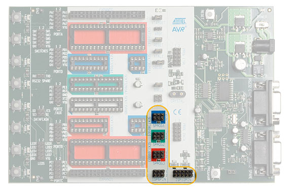
Because the programming interface is placed on different pins from part to part, 3 programming headers are used to route the programming signals to the correct pins. A 6-wire cable is supplied for connecting the ISP signals to the target ISP header. A color coding system, and a number system, is used to explain which target ISP header is used for each socket.
During ISP programming the 6-wire cable must always be connected to the header marked ISP6PIN. When programming parts in the blue sockets, connect the other end of the cable to the blue SPROG1 target ISP header. When programming parts in the green socket, use the green SPROG2 target ISP header. And when programming parts in the red sockets, use the red SPROG3 target ISP header. The table below shows which socket suits which AVR device, and which SPROG target ISP header to use for ISP programming.
The 6-wire cables should be connected directly from the ISP6PIN header to the correct SPROG target ISP header. The cable should not be twisted. A colored wire on the cable indicates pin one. Confirm that this is connected to pin one on each of the headers.
When programming 8-pin devices, note the following: Pin 1 is used both as RESET and as PB5 on some devices (ATtiny11, ATtiny12, ATtiny13, ATtiny15 and ATtiny45). Pin 1 on the 8-pin sockets SCKT3400D1 and SCKT3600A1 are connected to PB5. The RESET signal used during ISP programming is therefore not connected to pin 1 on these sockets. This signal must be connected by placing a wire between RST on the PORTE header and PB5 on the PORTB header. Use one 2-wire cable to connect the PB3 pin (pin 4) on the PORTB header to the XT1 pin (pin 7) on the PORTE/AUX header. This will connect the clock system to the AVR device.
| AVR devices | STK500 socket | Color | Number | Target ISP header |
|---|---|---|---|---|
|
AT90S1200 AT90S2313 ATtiny2313 |
SCKT3300D3 | Red | 3 | SPROG3 |
|
AT90S2323 AT90S2343 ATtiny12 ATtiny13 ATtiny22 ATtiny25 ATtiny45 ATtiny85 |
SCKT3400D1 | Blue | 1 |
SPROG1. Connect RST on PORTE to PB5 on PORTB. Connect XT1 on PORTE to PB3(XTAL1 on 2323) on PORTB. |
| ATtiny11 | SCKT3400D1 | Blue | 1 | High-Voltage programming only |
| ATtiny28 | SCKT3500D- | None | - | High-Voltage programming only |
|
AT90S4414 AT90S8515 ATmega161 ATmega8515 ATmega162 |
SCKT3000D3 | Red | 3 | SPROG3 |
|
AT89s51 AT89s52 |
SCKT3000D3 | Red | 3 |
SPROG3. These are MCS51 core compatible parts, they do not contain an AVR core. Only ISP programming is supported on these devices, no other functionality. |
|
AT90S4434 AT90S8535 ATmega16 ATmega163 ATmega164P ATmega32 ATmega323 ATmega324P ATmega644 ATmega644P ATmega1284P ATmega8535 |
SCKT3100A3 | Red | 3 | SPROG3 |
|
AT90S2333 AT90S4433 ATtiny48 ATtiny88 ATmega48(P) ATmega8 ATmega88(P) ATmega168(P) ATmega328P |
SCKT3200A2 | Green | 2 | SPROG2 |
| ATtiny15 | SCKT3600A1 | Blue | 1 |
SPROG1. Connect RST on PORTE to PB5 on PORTB. |
|
ATtiny26
ATtiny261 ATtiny461 ATtiny861 |
SCKT3700A1 | Blue | 1 | SPROG1Connect RST on PORTE to PB7 on PORTB. Connect XT1 on PORTE to PB4 on PORTB |
|
ATmega64 ATmega103 ATmega128 ATmega1281 ATmega2561 AT90CAN32 AT90CAN64 AT90CAN128 |
Use the STK501 Top Module | |||
|
ATmega165 ATmega165P ATmega169 ATmega169P ATmega325 ATmega325P ATmega329 ATmega329P ATmega645 ATmega649 |
Use the STK502 Top Module | |||
|
ATmega640 ATmega1280 ATmega2560 |
Use the STK503 Top Module | |||
|
ATmega1650 ATmega1690 ATmega3250 ATmega3250P ATmega3290 ATmega3290P ATmega6450 ATmega6490 |
Use the STK504 Top Module | |||
|
ATtiny24 ATtiny44 ATtiny84 |
Use the STK505 Top Module | |||
|
AT90PWM2 AT90PWM2B AT90PWM3 AT90PWM3B |
Use the STK520 Top Module | |||
|
AT90USB646 AT90USB647 AT90USB1286 AT90USB1287 |
Use the STK525 Top Module | |||
|
AT90USB82 AT90USB162 |
Use the STK526 Top Module | |||
| AT86RF401 | No socket support. External ISP-programming support through the AT86RF401-EK1 evaluation kit. | |||
| AVR devices | STK500 socket | Color | Number | Target ISP header |
The figure below shows an example of how ATmega8515 can be In-System Programmed. The 6-wire cable is connected from the ISP6PIN header to the red SPROG3 target ISP header, and the ATmega8515 part is inserted in the red socket marked SCKT3000D3.
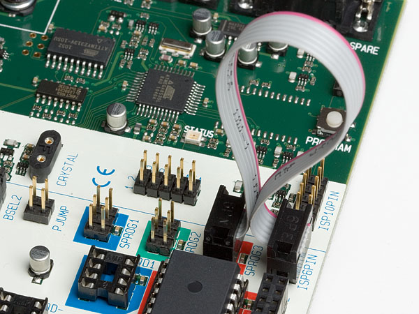
It is not necessary to remove the 6-wire cable from it’s ISP position while running a program in the AVR. The port pins used for ISP programming can be used for other purposes in your program.