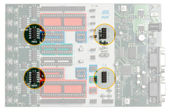
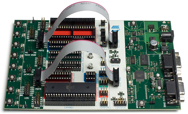
To use High-Voltage programming the programming signal must be routed to the Atmel AVR I/O pins. The two 10-wire cables supplied with the Atmel STK500 can be used to connect the PROG DATA header to the PORTB header and connecting the PROG CTRL header to the PORTD header as shown below.
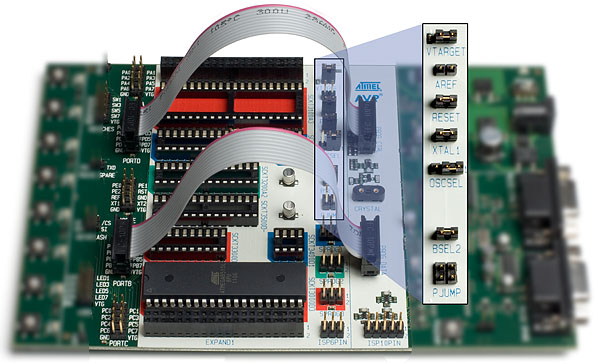
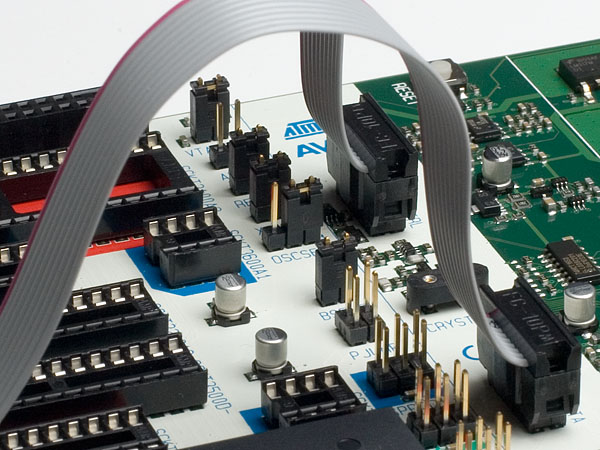
Some of the jumper settings on STK500 must be changed when using High-Voltage programming. The next figure explains these jumper settings.
HW setup for Parallel High-Voltage programming:
- 1.
Switch power off
- 2.
Place the device to program in its socket according to table in the "High Voltage Programming" section.
- 3.
Connect the headers PROGDATA and PORTB with the 10-wire cable
- 4.
Connect the headers PROGCTRL and PORTD with the 10-wire cable
- 5.
Mount jumper OSCSEL on pin 1 and 2 to select SW controlled clock
- 6.
Mount jumper XTAL1 to route the oscillator signal to the device
- 7.
Mount jumpers VTARGET and RESET
- 8.
When programming AT90S2333, AT90S4433, ATtiny48, ATtiny88, ATmega48, ATmega8, ATmega88 or ATmega168, mount both PJUMP jumpers. The 2-wire cables can be used instead of jumpers. See PJUMP Jumpers.
- 9.
Connect BSEL2 for the devices that requires that. See BSEL2 Jumper.
- 10.
Disconnect target system
- 11.
Switch power on
- 12.
Ensure that VTarget is between 4.5V and 5.5V before programming.
For complete description of jumper settings, see section "Jumper settings".
Note : Remove the HW setup for High-Voltage programming before starting a debug session.