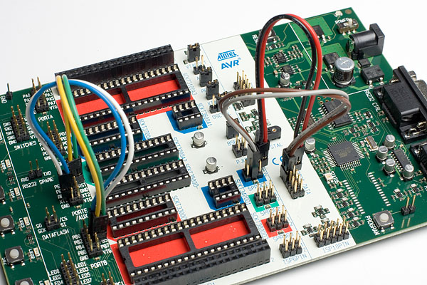
The 8 pin Atmel AVRs have too few pins to use parallel communication during High-Voltage programming. They use serial communcation instead. This means that less signals have to be routed. HW setup for serial High-Voltage programming is:
- 1.
Switch power off
- 2.
Place the device to program in its socket according to the table in the High Voltage Programming section.
- 3.
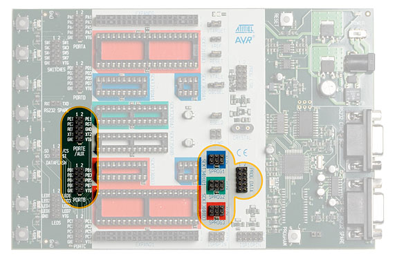
Mount jumper OSCSEL on pin 1 and 2 to select SW controlled clock
- 4.
Mount jumper XTAL1 to route the oscillator signal to the device
- 5.
Mount jumpers VTARGET and RESET
- 6.
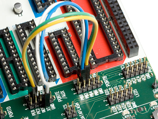
Use on 2-wire cable to connect the PB3 pin (pin 4) on the PORTB header to the XT1 pin (pin 7) on the PORTE / AUX header. This will connect the clock system to the AVR device.
- 7.
Use another 2-wire cable to connect the PB5 pin (pin 6) on the PORTB header to the RST pin (pin 4) on the PORTE / AUX header. This will connect the reset system to the AVR device.
- 8.
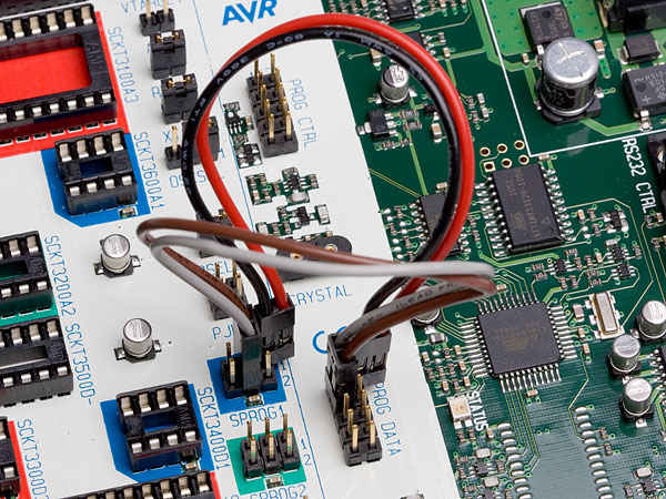
Use a third 2-wire cable to connect the PB0 and PB2 pins (pins 4 and 3) on the SPROG1 header to the DATA0 and DATA2 pins (pins 1 and 3) on the PROG DATA header.
- 9.
Use the last 2-wire cable to connect the PB1 pin (pin 1) on the SPROG1 header to the DATA1 pin (pin 2) on the PROG DATA header.
- 10.
Switch power on and you are ready to program
- 11.
Ensure that VTarget is between 4.5V and 5.5V before programming.
All connections are shown below.