The Atmel STK500 starter kit is shipped with an AT90S8515-8PC microcontroller in the socket marked SCKT3000D3. The default jumper settings will allow the microcontroller to execute using the clock source and voltage regulator system on the STK500 board.
The microcontroller is programmed with a test program that toggles the LEDS. The test program in the AT90S8515 is similar to the example application code described in section "Example Applications". Connect the LEDS and switches, and power up the STK500 to run the test program in the AT90S8515.
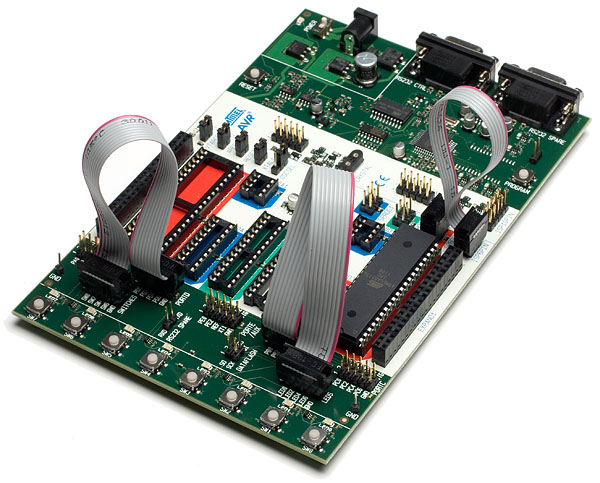
Use the supplied 10-pin cables to connect the header marked PORTB with the header marked LEDS, and connect the header marked PORTD with the header marked SWITCHES. The connections are shown on the figure below.
An external 10-15V DC power supply is required. The input circuit is a full bridge rectifier, and the STK500 automatically handles both positive or negative center connector, if a positive center connector is used, it can in some cases be impossible to turn the STK500 off since the power switch then disconnects the GND terminal, in this case GND can be supplied through the RS-232 cable shield if connected or through alternative GND connections. Connect the power cable between a power supply and the STK500. Apply 10-15 VDC to the power connector. The power switch turns the STK500 main power on and off. The red LED is lit when power is on, and the status LEDS will go from red, via yellow to green. The green LED indicates that the Target V CC is present. The program now running in the AT90S8515 will respond to pressed switches by toggling the LEDs.