The LEDs are labeled LED0 to LED7. The corresponding pins on the LEDS header have the same labels.
The LED hardware is shown in the figure below. The transistor circuit ensures the LED brightness is independent of target voltage.
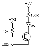
To light one of the LEDs, the corresponding pin found on the LEDs header must be pulled to GND.
To control the LEDs from the Atmel AVR, connect a cable between the LEDS header and one of the PORT headers. Use a 10-wire cable to connect to all eight LEDs or a two-wire cable to control one or two LEDs.
Just like the PORT headers, the LEDS header has GND and VTG on pin 9 and 10. When using a 10-wire cable, make sure the pin one indication on the cable (red wire, triangular arraow pointing on pin one) aligns to pin 1 on both the LEDs header and PORT pin header.
The I/O port connected to LEDn will not source any significant current when LEDn is driven high, but it will sink a current of approximately 18mA when LEDn is pulled to GND.