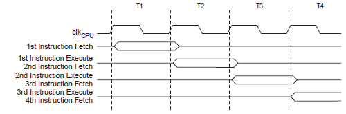
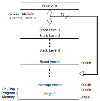
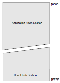
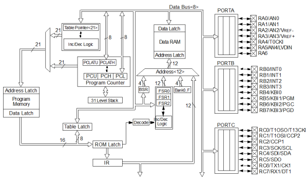
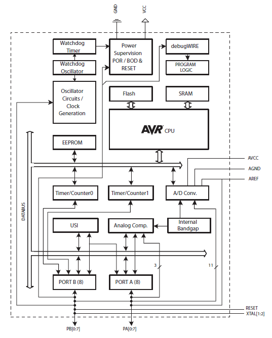
The microcontroller (MCU) has on-chip program memory (Figure 1 or Figure 2) for the firmware, or coded instructions, to run a program (Figure 3 or Figure 4). A Program Counter (PC) is used to address program memory, including Reset and interrupt addresses. A hardware stack is used with call and return instructions in code, so it works with, but is not part of, program memory. Device data sheets describe the details of program memory operation, vectors and the stack.
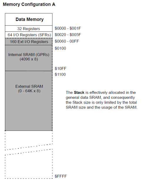
The microcontroller also has data, or File Register, memory. This memory consists of Special Function Registers (SFRs) and General Purpose Registers (GPRs). SFRs are registers used by the CPU and peripheral functions for controlling the desired operation of the device. GPRs are for storage of variables that the program will need for computation or temporary storage. Some microcontrollers have additional data EEPROM memory. As with program memory, device data sheets describe the details of data memory use and operation.
| Bank 0 | File Address | Bank 1 | File Address | Bank 2 | File Address | Bank 3 | File Address |
|---|---|---|---|---|---|---|---|
| Indirect addr. (1) | 00h | Indirect addr. (1) | 80h | Indirect addr. (1) | 100h | Indirect addr. (1) | 180h |
| TMR0 | 01h | OPTION_REG | 81h | TMR0 | 101h | OPTION_REG | 181h |
| PCL | 02h | PCL | 82h | PCL | 102h | PCL | 182h |
| STATUS | 03h | STATUS | 83h | STATUS | 103h | STATUS | 183h |
| FSR | 04h | FSR | 84h | FSR | 104h | FSR | 184h |
| PORTA | 05h | TRISA | 85h | PORTA | 105h | TRISA | 185h |
| PORTB | 06h | TRISB | 86h | PORTB | 106h | TRISB | 186h |
| PORTC | 07h | TRISC | 87h | PORTC | 107h | TRISC | 187h |
| 08h | 88h | 108h | 188h | ||||
| 09h | 89h | 109h | 189h | ||||
| PCLATH | 0Ah | PCLATH | 8Ah | PCLATH | 10Ah | PCLATH | 18Ah |
| INTCON | 0Bh | INTCON | 8Bh | INTCON | 10Bh | INTCON | 18Bh |
| PIR1 | 0Ch | PIE1 | 8Ch | EEDAT | 10Ch | EECON1 | 18Ch |
| PIR2 | 0Dh | PIE2 | 8Dh | EEADR | 10Dh | EECON2(1) | 18Dh |
| TMR1L | 0Eh | PCON | 8Eh | EEDATH | 10Eh | 18Eh | |
| TMR1H | 0Fh | OSCCON | 8Fh | EEADRH | 10Fh | 18Fh | |
| T1CON | 10h | OSCTUNE | 90h | 110h | 190h | ||
| TMR2 | 11h | 91h | 111h | 191h | |||
| T2CON | 12h | PR2 | 92h | 112h | 192h | ||
| SSPBUF | 13h | SSPADD(2) | 93h | 113h | 193h | ||
| SSPCON | 14h | SSPSTAT | 94h | 114h | 194h | ||
| CCPR1L | 15h | WPUA | 95h | WPUB | 115h | 195h | |
| CCPR1H | 16h | IOCA | 96h | IOCB | 116h | 196h | |
| CCP1CON | 17h | WDTCON | 97h | 117h | 197h | ||
| RCSTA | 18h | TXSTA | 98h | VRCON | 118h | 198h | |
| TXREG | 19h | SPBRG | 99h | CM1CON0 | 119h | 199h | |
| RCREG | 1Ah | SPBRGH | 9Ah | CM2CON0 | 11Ah | 19Ah | |
| 1Bh | BAUDCTL | 9Bh | CM2CON1 | 11Bh | 19Bh | ||
| PWM1CON | 1Ch | 9Ch | 11Ch | 19Ch | |||
| ECCPAS | 1Dh | 9Dh | 11Dh | PSTRCON | 19Dh | ||
| ADRESH | 1Eh | ADRESL | 9Eh | ANSEL | 11Eh | SRCON | 19Eh |
| ADCON0 | 1Fh | ADCON1 | 9Fh | ANSELH | 11Fh | 19Fh | |
| General
Purpose
Register 96 Bytes |
20h | General
Purpose
Register 80 Bytes |
A0h | General
Purpose
Register 80 Bytes |
120h | 1A0h | |
| EFh | 16Fh | ||||||
| accesses 70h-7Fh |
F0h | accesses 70h-7Fh |
170h | accesses 70h-7Fh |
1F0h | ||
| 7Fh | FFh | 17Fh | 1FFh | ||||
|
Empty table cells: Unimplemented data memory locations, read as ‘0’. |
|||||||
In addition to memory, the microcontroller has a number of peripheral device circuits on the same chip. Some peripheral devices are called input/output (I/O) ports. I/O ports are pins on the microcontroller that can be used as outputs and driven high or low to send signals, blink lights, drive speakers – just about anything that can be sent through a wire. Often these pins are bidirectional and can also be configured as inputs, allowing the program to respond to an external switch, a sensor, or to communicate with some external device.
To design such a system, choose which peripherals are necessary for the application.
The following is a list of common peripherals:
- Analog-to-Digital Converters (ADCs) allow microcontrollers to connect to sensors and receive changing voltage levels.
- Serial communication peripherals that allow streaming communications over a few wires to another microcontroller, to a local network, or to the Internet.
- Peripherals on the PIC MCU called “timers” accurately measure signal events and generate and capture communications signals, produce precise waveforms, even automatically reset the microcontroller if it gets “hung” or lost due to a power glitch or hardware malfunction.
- Other peripherals detect when the external power is dipping to dangerous levels, so that the microcontroller can store critical information and safely shut down before power is completely lost.
The peripherals, and the amount of memory an application needs to run a program, largely determine which PIC MCU to use. Other factors could include the power consumed by the microcontroller and its “form factor,” i.e., the size and characteristics of the physical package that must reside on the target design.
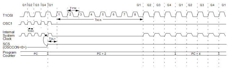
A microcontroller becomes active when power is applied and an oscillator begins generating a clocking signal. Depending on the microcontroller, there may be several internal and external oscillator operational modes.