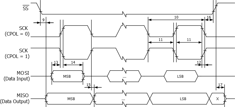
| Description | Mode | Min. | Typ | Max | Units |
|---|---|---|---|---|---|
| SCK period | Master | - | See Table. Relationship Between SCK and the Oscillator Frequency in "SPCR – SPI Control Register" | - | ns |
| SCK high/low | Master | - | 50% duty cycle | - | |
| Rise/Fall time | Master | - | 3.6 | - | |
| Setup | Master | - | 10 | - | |
| Hold | Master | - | 10 | - | |
| Out to SCK | Master | - | 0.5 • tsck | - | |
| SCK to out | Master | - | 10 | - | |
| SCK to out high | Master | - | 10 | - | |
| SS low to out | Slave | - | 15 | - | |
| SCK period | Slave | 4 • tck | - | - | |
| SCK high/low(1) | Slave | 2 • tck | - | - | |
| Rise/Fall time | Slave | - | - | 1600 | |
| Setup | Slave | 10 | - | - | |
| Hold | Slave | tck | - | - | |
| SCK to out | Slave | - | 15 | - | |
| SCK to SS high | Slave | 20 | - | - | |
| SS high to tri-state | Slave | 10 | - | ||
| SS low to SCK | Slave | 2 • tck | - | - |
Note: In SPI Programming mode the minimum SCK high/low period is:
- 2 • tCLCLCL for fCK < 12MHz
- 3 • tCLCL for fCK > 12MHz
Figure 1. SPI Interface Timing Requirements
(Master Mode)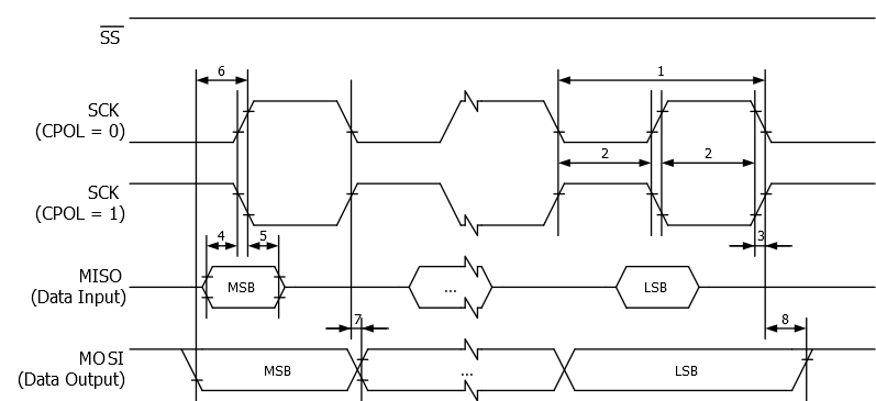
Figure 2. SPI Interface Timing Requirements
(Slave Mode)