The 32 KHz crystal oscillator driver of AVR microcontrollers is optimized for very low power consumption, and thus the crystal driver strength is limited. Overloading the crystal driver may cause the oscillator to not start, or it may be affected (stopped temporarily) e.g., due to a noise spike or increased capacitive load caused by the contamination or proximity of a hand.
This means that care must be taken when selecting and testing the crystal to ensure proper robustness in your application. The two important crystal parameters are Equivalent Series Resistance (ESR) and Load Capacitance (CL).
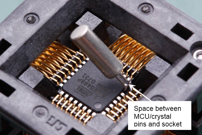
When doing measurements on crystals, the crystal should be placed as close as possible to the 32 KHz oscillator pins to reduce parasitic capacitance. In general, we always recommend doing the measurement in your final application. For initial testing of the crystal, however, using a starter kit (e.g., STK600) will work fine.
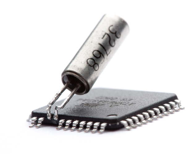
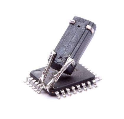
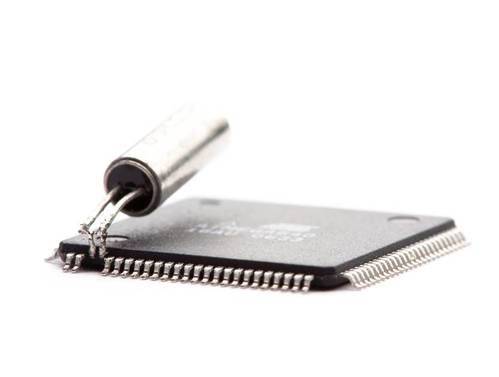
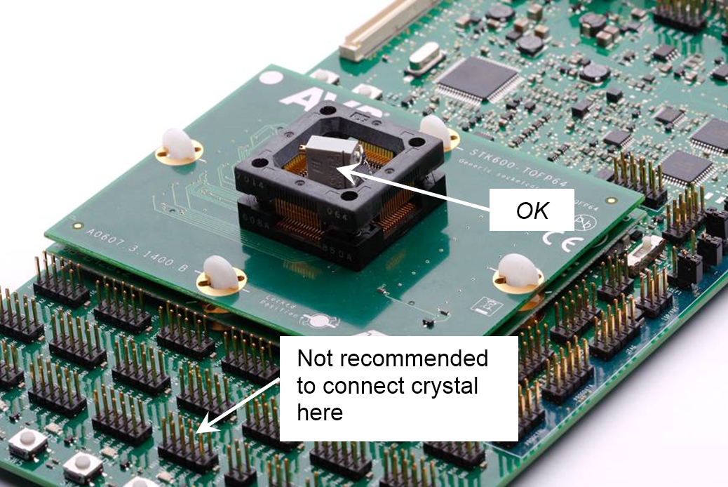
We do not recommend connecting the crystal to the XTAL/TOSC output headers at the end of the STK600, as shown in Figure 1, because the signal path will be very sensitive to noise and thereby add extra capacitive load. Soldering the crystal directly to the leads, however, will give good results. To avoid extra capacitive load from the socket and routing on the STK600, we recommend bending the XTAL/TOSC leads upwards, as shown in Figure 2 and Figure 3, so they do not touch the socket. Crystals with leads (hole mounted) are easier to handle, but it is also possible to solder SMD directly to the XTAL/TOSC leads by using pin extensions, as shown in Figure 4. Soldering crystals to packages with narrow pin pitch is also possible, as shown in Figure 5, but is a bit trickier and requires a steady hand.
Since capacitive load will have a great effect on the oscillator, you should not probe the crystal directly unless you have high-quality equipment intended for crystal measurements. Standard 10X oscilloscope probes impose a loading of 10-15 pF and will have a high impact on the measurements. Touching the pins of a crystal with a finger or a 10X probe can be sufficient to start or stop oscillations or give false results. Firmware for outputting the clock signal to a standard I/O pin is supplied with this application note. Unlike the XTAL/TOSC pins, I/O pins can be probed with standard 10X oscilloscope probes without affecting the measurements. More details can be found in Chapter 4, Test Firmware.