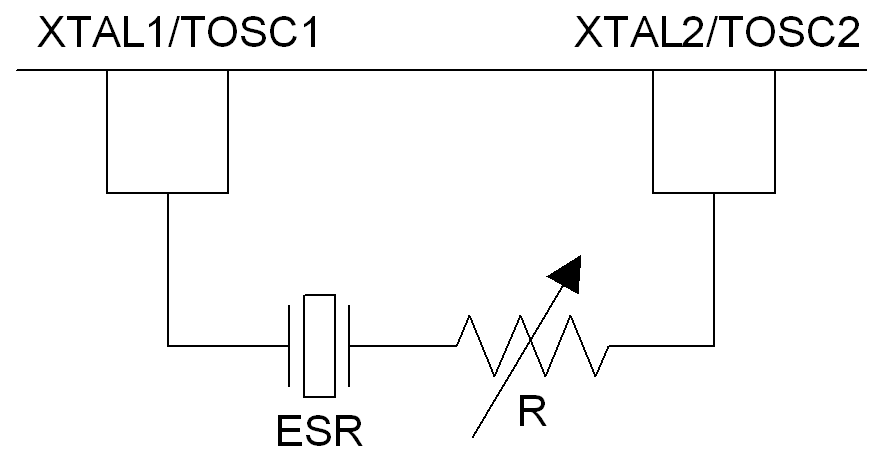
The negative resistance test finds the margin between the crystal amplifier load used in your application and the maximum load. At the maximum load, the amplifier will choke and the oscillations will stop. This point is called the oscillator allowance (OA). The oscillator allowance can be found by temporarily adding a variable series resistor between the amplifier output (XTAL2/TOSC2) lead and the crystal, as shown in Figure 2. The series resistor should be increased until the crystal stops oscillating. The oscillator allowance will then be the sum of this series resistance, RMAX, and the ESR. We recommend using a potentiometer with a range of at least ESR < RPOT < 5 ESR.
Finding a correct RMAX value can be a bit tricky because no exact oscillator allowance point exists. Before the oscillator stops, you may observe a gradual frequency reduction, and there may also be a start-stop hysteresis. After the oscillator stops, you will need to reduce the RMAX value by 10-50 kΩ before oscillations resume. We recommend performing a power cycling each time after the variable resistor is increased. RMAX will then be the resistor value where the oscillator does not start after a power cycling. Note that the start-up times will be quite long at the oscillator allowance point, so be patient.
We recommend using a high-quality potentiometer with low parasitic capacitance (an SMD potentiometer suitable for RF will usually give the best results). However, if you are able to achieve good oscillator allowance/RMAX with a cheap potentiometer, you will be safe.
When the maximum series resistance is found, you can find the safety factor from Figure 3. Various MCU and crystal vendors operate with different safety factor recommendations. The safety factor is intended to add a margin for negative effects of different variables such as oscillator amplifier gain, change due to the power supply and temperature variations, process variations, and load capacitance. The 32 KHz oscillator amplifier on AVR microcontrollers is temperature and power compensated, and so by having these variables more or less constant, we can reduce the requirements for the safety factor compared to other MCU/IC manufacturers. The safety factor recommendations can be found in Table 1.
| Safety Factor | Recommendation |
|---|---|
| 5< | Excellent |
| 4 | Very good |
| 3 | Good |
| <3 | Not recommended |