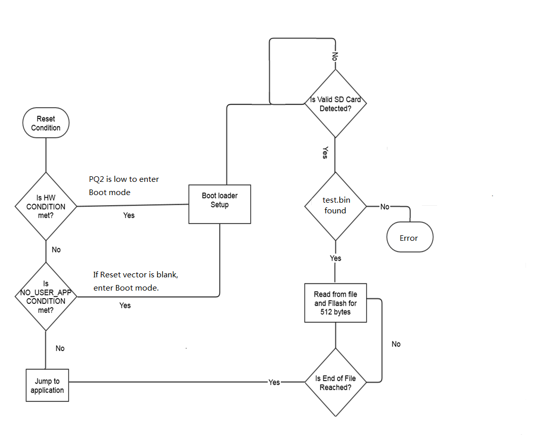
MCU executes from the bootloader section at each reset/power-on sequence. Initially it checks the status on a configurable BOOT_LOAD_PIN. The BOOT_LOAD_PIN needs to be configured as input with pull-up before checked.
- If the pin is pulled low, enter boot mode
- If the pin is high, read the address
0x0000 of application section
- If 0xFFFF is read out, the application section is empty and will enter boot mode
- If not, jump to the application section and run the application code
Once entering boot mode, the following procedures are to be performed step by step.
- Initialize the on-board ports, system clock, SD MMC, FatFs, etc.
- Keep detecting SD card presence until a card is detected
- Turn on LED0
- Mount the SD card for file system access
- Open the file test.bin
- Read file for a block of MAX_BUF_SIZE (configurable)
- Program the data to application flash section starting from 0x0000
- Repeat read and program till the end of file
- Turn off LED0
- Remap the reset vector to the application section
- Jump to the starting address at 0x0000
The firmware chart is shown in the figure below.
Figure 1. Firmware Chart