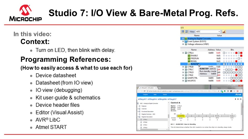
This section describes how you would typically write code in Studio 7, independent of a software configuration tool or framework, i.e. bare-metal. This is covered both as video (linked below) and hands-on document. The main focus is on each of the relevant programming references, how each is accessed, and what each is used for. The project context is to turn ON an LED, then blink with a delay. Although the ATtiny817 Xplained Pro is used the principles are general enough to use with any kit in Studio 7, though the principles apply to most devices supported in Studio 7.
Video: I/O View and Bare-metal programming references
The list below is an overview of the programming references which are typically used. Particular emphasis is placed on I/O View, which provides a way to navigate data sheet register descriptions when editing or debugging, as well as to understand the current configuration when debugging. This second use of I/O view when debugging is also used to test new register configurations.
This topic is closely related to both Debugging 3: I/O View Memory View and Watch as well as Editor: Writing and Re-Factoring Code (Visual Assist).
- Device data sheet
- Data sheet (from I/O view)
- Kit user guide and schematics
- I/O View (debugging)
- Editor (Visual Assist)
- Device header files
- AVR Libc (AVR specific)
- Atmel START: ATtiny817 project
#include <avr/io.h>
#define F_CPU 3333333
#include <util/delay.h>

int main(void)
{
	PORTB.DIR = PIN4_bm;

    while (1)
    {
		_delay_ms(500);
		PORTB.OUTTGL = PIN4_bm;
    }
}
Device Data Sheet (PDF)
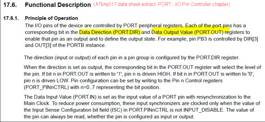
Although I/O View allows easy access to navigate the data sheet at a register level, the PDF version still has a role. The device data sheet, in PDF format, tends to be used at least to get an understanding of the peripheral, through the block diagram and functional description. For example, to understand the PORT peripheral of the ATtiny817, we consulted the PORT Block Diagram and Functional Description > Principle of operation sections of the data sheet. These two sections together, connecting the description to the diagram, give a basic understanding of the PORT peripheral.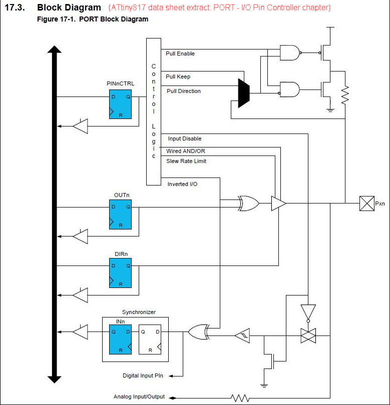
I/O View Data Sheet
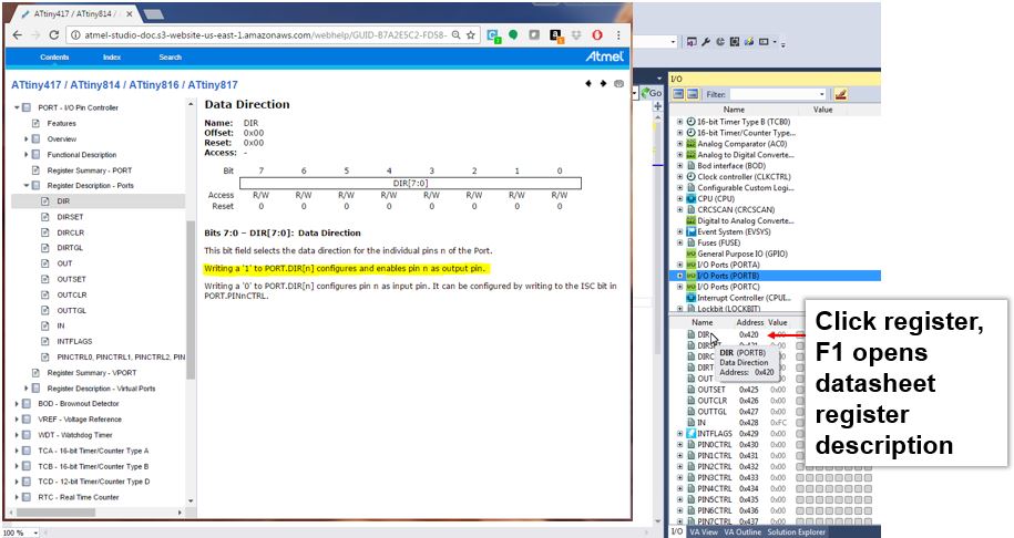
Studio 7 allows to easily access the data sheet register descriptions by clicking F1 on the relevant register description. The HTML version of the data sheet opens online (by default). The data sheet will open in the context of the relevant register description.- 1.Writing a '1' to PORT.DIR[n] configures and enables pin n as an output pin.
- 2.If OUT[n] is written to '0', pin n is driven low.
I/O View (Debugging)
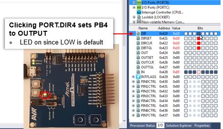
This functionality can directly be tested by starting a debug session, using Start Debugging and Break. So we are now able to begin testing functionality, as shown in the image below.- 1.Verify that writing a '1' to PORT.DIR4, sets pin as OUTPUT, LOW by default to LED turns ON.
- 2.Verify that writing a '1' to PORT.OUT4, turns OFF the LED.
| Button | Functionality | Keyboard Shortcut |
|---|---|---|
 |
Start Debugging and Break | Alt + F5 |
 |
Attach to Target | |
 |
Start Debugging | F5 |
 |
Break All | Ctrl + Alt + Break |
 |
Start Without Debugging | Ctrl + F5 |
Downloading Studio 7 Documentation
The data sheet can also be downloaded by using the Studio 7 help system. In this case, a similar functionality will work offline. This is described here: Downloading Offline Documentation.Atmel Studio 7 Editor (Visual Assist)
Specifically in the video related to this section, the editor is used for the following.
Device Header Files
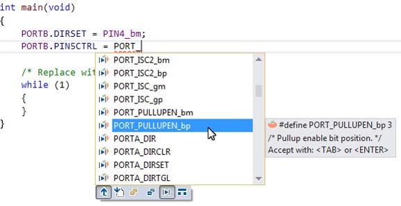
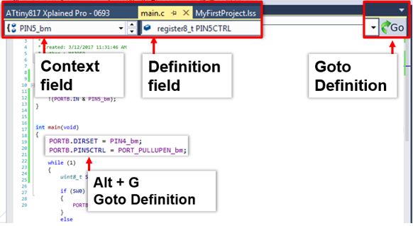
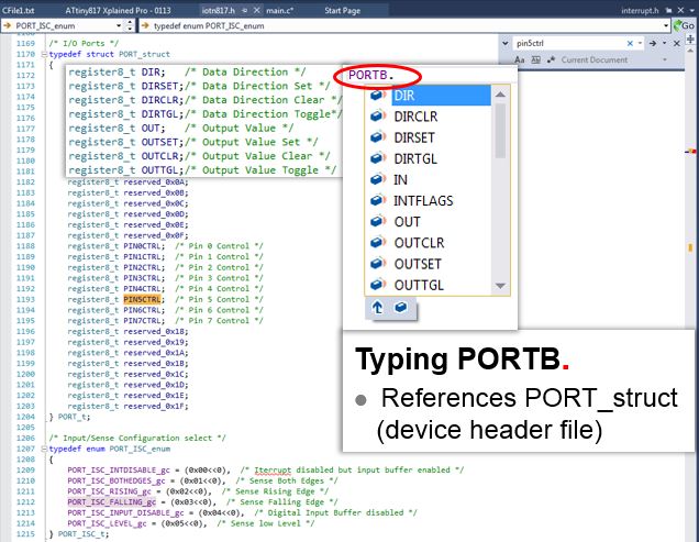
Through the Goto Definition functionality of the editor, it is easy to access the MCU device header files, i.e. by clicking on any register and then clicking on the goto button, or typing Alt+G. Writing PORTB. gives a suggestion list of potential registers, from the PORT structure, shown in figure Suggestion lists and the MCU device header files. For more information about how the AVR header files are structured, see AVR1000 for more information.
Kit Schematics and User Guide
The kit schematics and user guide are useful to understand the MCU pin connections on the kit. Full schematics and kit design files, such as Gerbers, are available on www.microchip.com, on the kit's product page.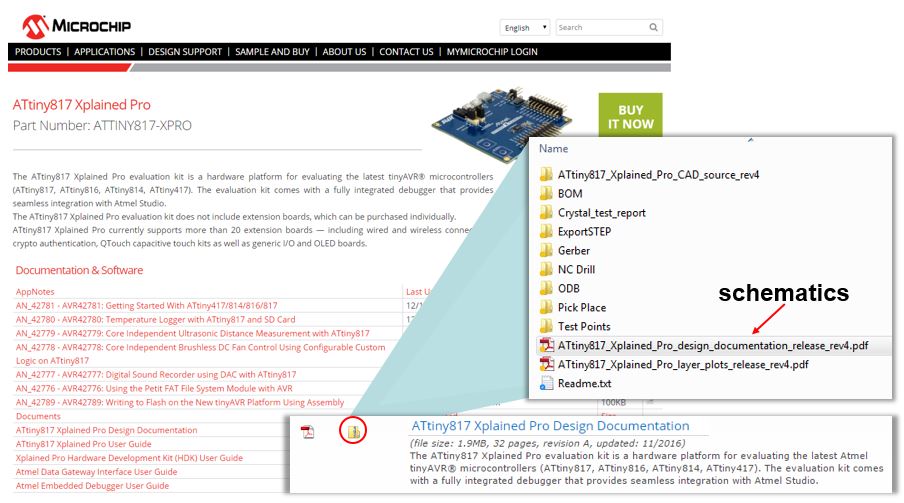

| Silkscreen Text | ATtiny817 GPIO Pin |
|---|---|
| LED0 | PB4 |
| SW0 | PB5 |
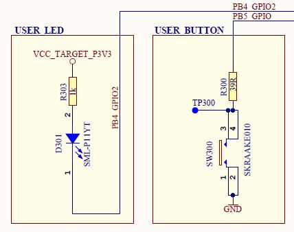
- The LED can be turned ON by driving PB4 low.
- SW0 is connected directly to GND and to PB5 through a current limiting resistor.
- SW0 does not have an external pull-up resistor.
- SW0 will be read as '0' when pushed and as '1' when released, if the ATtiny817 internal pull-up is enabled.
AVR Libc
All the references covered to this point are just as relevant for SAM as for AVR, however, as the name suggests, this one is specific to AVR. AVR Libc is a Free Software project whose goal is to provide a high-quality C library for use with GCC on AVR microcontrollers. Together, avr-binutils, avr-gcc, and avr-libc form the heart of the Free Software toolchain for the AVR microcontrollers. Further, they are accompanied by projects for in-system programming software (avrdude), simulation (simulavr), and debugging (avr-gdb, AVaRICE).
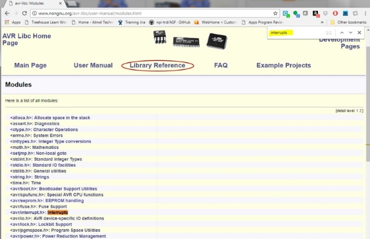
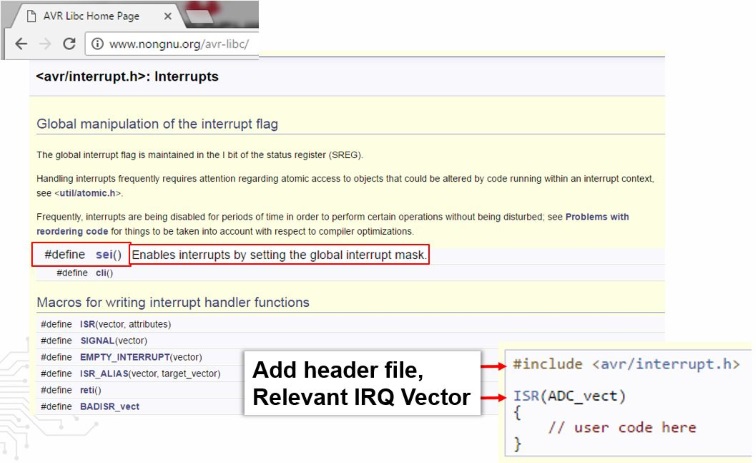
The library reference is usually a quick interface into AVR Libc, as shown in Figure 10. One can quickly search the page for a relevant library. Relevant header files, which should be added to the project, are indicated in the module name. For example searching for 'interrupts', the relevant include will be #include <avr/interrupt.h>. Clicking into the module, a list of available functions and relevant interrupt callbacks can be found, as shown in Figure 11.
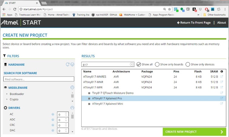
Atmel START
Atmel START is a web-based software configuration tool, for various software frameworks, which helps you getting started with MCU development. Starting from either a new project or an example project, Atmel START allows you to select and configure software components (from ASF4 and AVR Code), such as drivers and middleware to tailor your embedded application in a usable and optimized manner. Once an optimized software configuration is done, you can download the generated code project and open it in the IDE of your choice, including Studio 7, IAR Embedded Workbench, Keil μVision, or simply generate a make-file.
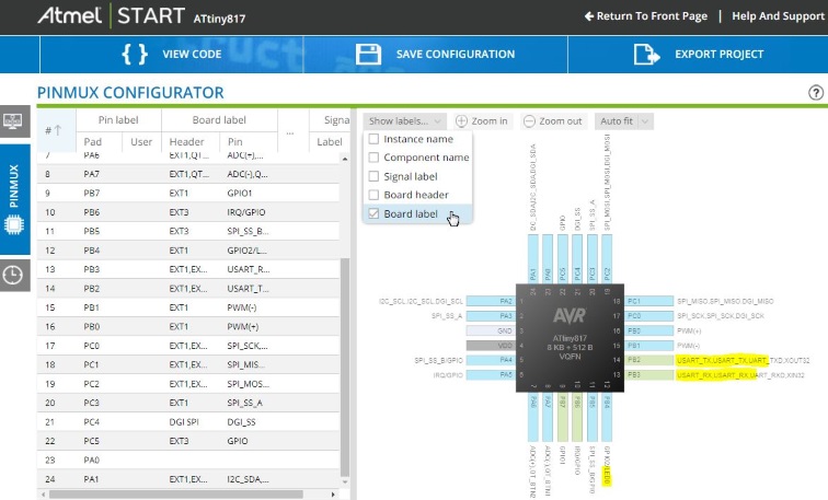
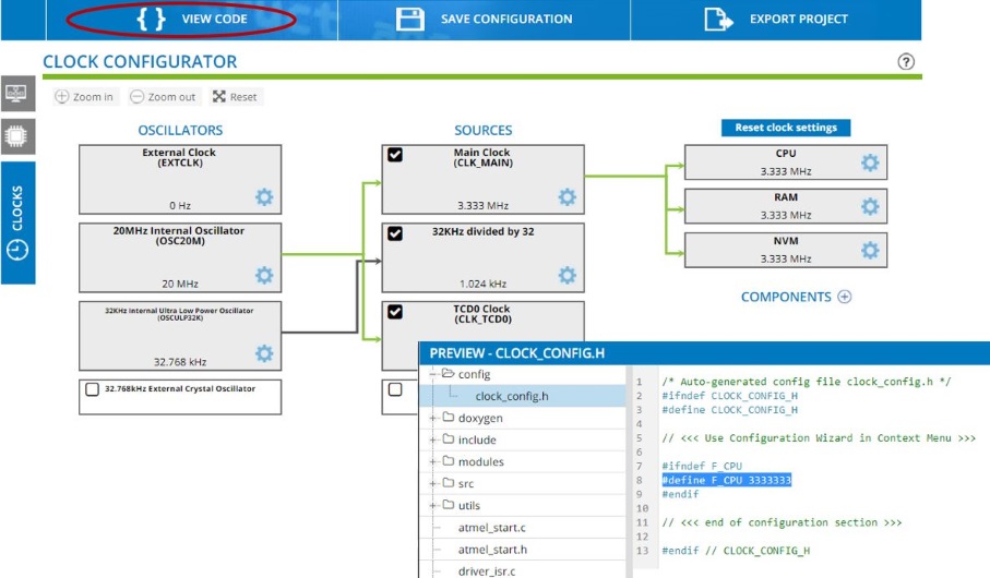
Although Atmel START is a tool for MCU and software configuration, it can still be useful even in bare-metal development, i.e. writing code from scratch using the list of programming references described in this section. Creating a new project for the kit you are using, can be a useful alternative to the board schematic, using the PINMUX view. In addition, the CLOCKS view can be useful to check the default clocks of a device. Furthermore, viewing the configuration code, useful pieces can be pasted back into your project. For example, the AVR Libc delay functions require that the clock frequency is defined, as shown in Figure 14. For the ATtiny817 this default value would be: #define F_CPU 3333333.