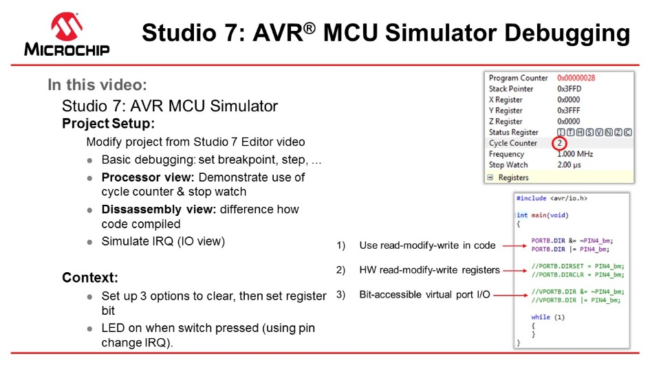
This section will demonstrate the use of the AVR Simulator key features, such as: Cycle Counter, Stopwatch (only available in the simulator), and basic debugging (setting breakpoints and stepping through code). We will also show how to simulate interrupts.
Video: AVR Simulator Debugging
The code used in the video above was written in the video: Editor: Writing and Re-Factoring Code (Visual Assist).
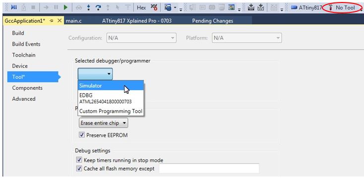
To associate the simulator with the project, click on the Tool icon  , then
select Simulator.
, then
select Simulator.
The Cycle Counter and Stopwatch is only available with the
simulator. To use these, first, click Start Debugging and Break
 to
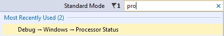
start a debug session and then open the Processor Status window by typing
'Processor' into the quick-launch bar and hitting enter (or this can be found under
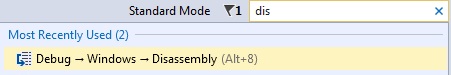
Debug > Windows > Processor Status). Similarly, the Disassembly window can
also be opened.
to
start a debug session and then open the Processor Status window by typing
'Processor' into the quick-launch bar and hitting enter (or this can be found under
Debug > Windows > Processor Status). Similarly, the Disassembly window can
also be opened.
The AVR Simulator is using models based on the same RTL code used to make the real device. This makes the Cycle Counter both bug and delay accurately. Note that the Stop Watch is related to the Frequency, which you can set by double-clicking on the value and entering the clock frequency you would like to use.
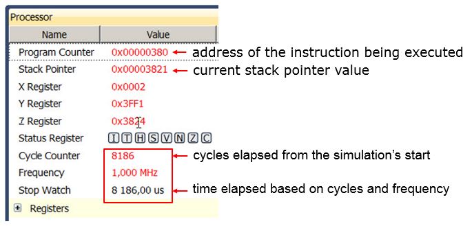
The Cycle Counter can be reset by clicking on the value and entering 0. Values in the Processor Status window are updated every time the program breaks, similar to the I/O view. Then running to a breakpoint.
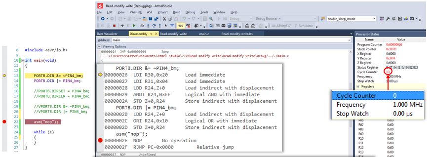
Note the difference in generated assembly code between the SW read-modify-write (above) and the virtual port registers (see below).
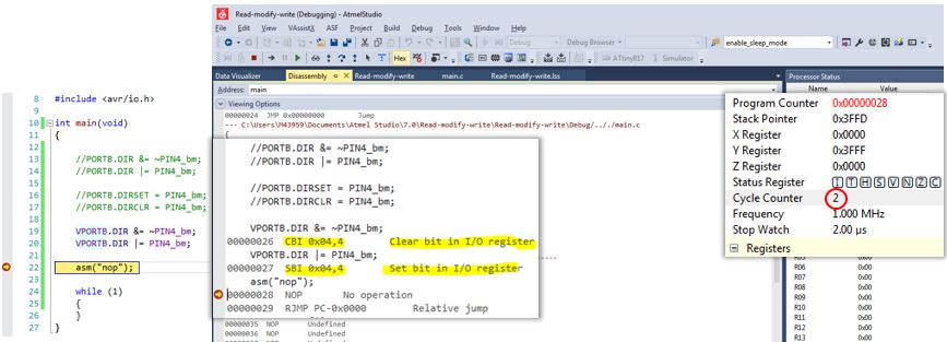
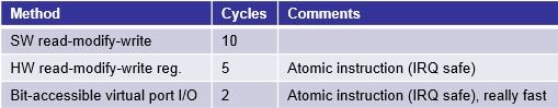
The result of comparing these three methods are summarized in the table below:
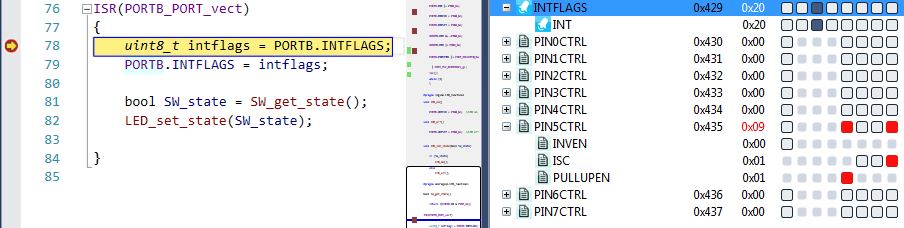
As shown below the ISR is hit. Note that the INTERRUPT still needs to be enabled, as shown in the write to PORTB.PIN5CTRL in the code below.
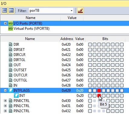
The pin change IRQ could also have been triggered by writing to the Port Input register in the I/O view. Writing a bit in the Port Input register is the same as applying that value to the physical pin of the device package. The internal Port logic will then trigger the interrupt if it is configured accordingly.
Most of the standard debugging features of Studio 7 are available when using the simulator, and those features will also be available on devices that lack on-chip debugging capabilities and cannot be debugged using hardware debuggers. See the debugging sections of this Getting Started guide.
Code Used to Demonstrate AVR Simulator (Written for ATtiny187)
#include <avr/io.h>
#include <stdbool.h>
#include <avr/interrupt.h>

void LED_on();
void LED_off();
bool SW_get_state();
void LED_set_state(bool SW_state);

int main(void)
{
	PORTB.DIR &= ~PIN4_bm;
	PORTB.DIR |= PIN4_bm;

	PORTB.DIRCLR = PIN4_bm;
       PORTB.DIRSET = PIN4_bm;

       VPORTB.DIR &= ~PIN4_bm;
       VPORTB.DIR |= PIN4_bm;

	PORTB.PIN5CTRL |= PORT_PULLUPEN_bm | PORT_ISC_BOTHEDGES_gc;
	sei();

    while (1)
    {
    }
}

#pragma region LED_functions
void LED_on()
{
	PORTB.OUTCLR = PIN4_bm;  //LED on
}

void LED_off()
{
	PORTB.OUTSET = PIN4_bm;  //LED off
}

void LED_set_state(bool SW_state)
{
	if (SW_state)
	{
		LED_on();

	}
	else
	{
		LED_off();

	}
}
#pragma endregion LED_functions

bool SW_get_state()
{
	return !(PORTB.IN & PIN5_bm);
}

ISR(PORTB_PORT_vect)
{
	uint8_t intflags = PORTB.INTFLAGS;
	PORTB.INTFLAGS = intflags;

	bool SW_state = SW_get_state();
	LED_set_state(SW_state);

}