To start with, implement a sampling of the light sensor and stream the data
to the host computer to be able to view the data as a plot in a graph.
Todo:
- Make a new project in Atmel Studio (File → New → Project → GCC C Executable Project)
- Replace the content of the automatically generated main.c file with the code below
#include <avr/io.h>
uint16_t adc_value = 0;
void adc_init(void){
	// Internal 1.5V reference, ADC0 as single ended input
	ADMUX = (1 << REFS1);
	// Enable the ADC,
	ADCSRA |= (1<<ADEN);
	// Check that the reference is OK
	while (0x00 == (ADCSRB & (1 << REFOK)));
}
uint16_t adc_sample(void){
	// Trigger an ADC conversion
	ADCSRA |= (1<<ADSC);
	// Wait for conversion to finish
	while (0x00 == (ADCSRA & (1 << ADIF)));
	// Clear the interrupt flag
	ADCSRA |= (1 << ADIF);
	return (ADC);
}
void spi_init(void){
	// Slave select (PB0), MOSI (PB2) and SCK (PB1) as output
	DDRB |= (1<<PINB0) | (1<<PINB2) | (1<<PINB1);
	//Slave select high (inactive)
	PORTB |= (1<<PINB0);
	// Master mode, enable SPI module.
	// Clock polarity and phase is kept at default (Sample on rising edge)
	SPCR = (1<<SPE) | (1<<MSTR);
}
void spi_send(uint8_t data){
	// Slave select low
	PORTB &= ~(1<<PINB0);
	// Write data to shift register
	SPDR = data;
	// Wait for the transmission to complete
	while (0x00 == (SPSR & (1<<SPIF)));
	// Slave select high
	PORTB |= (1<<PINB0);
}
int main(void){
	adc_init();
	spi_init();
	while (1){
		adc_value = adc_sample();
		// Send the ADC value over SPI to the host
		// Only the 8 lower bits contain useful data
		spi_send(adc_value & 0xFF);
	}
}
The code samples the ADC continuously and sends the data over the SPI interface to the EDBG (Embedded Debugger) on the ATmega256RFR2 Xplained Pro board. The EDBG then sends the SPI data over DGI to the host computer. The ATmega256RFR2 ADC is 10-bit but only the lower 8 bits contain useful data in this example.
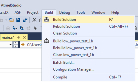
Todo: Build
the project/solution (F7).
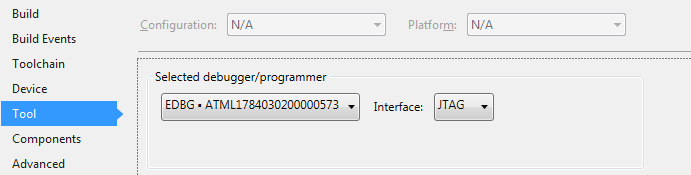
Todo:
- Open the project properties (right click the project in the Solution Explorer and select Properties)
- On the Tool tab, select the appropriate tool and interface
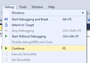
Todo: Program the application into the target and start the debugging by selecting
Continue (F5).
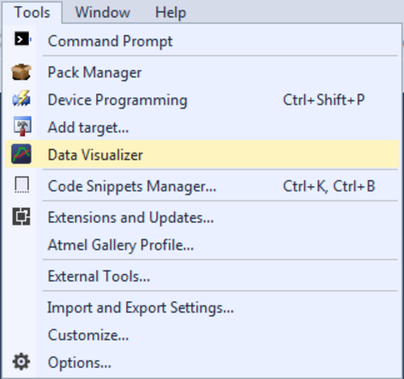
Todo: Open
the Data Visualizer as an extension inside Atmel Studio by selecting it in the
Tools menu.