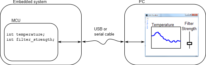
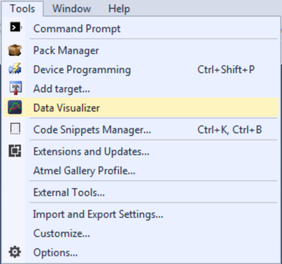
This chapter gives an overview of the main modules/features of the Data Visualizer. Each module is described in a separate chapter with technical details of the module, and includes an example or use case showing how to use the module. As each chapter is self-contained, it is possible for the user to quickly identify and select the chapter/module of interest.
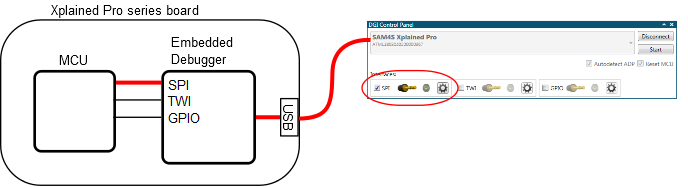
Data Gateway Interface (DGI)
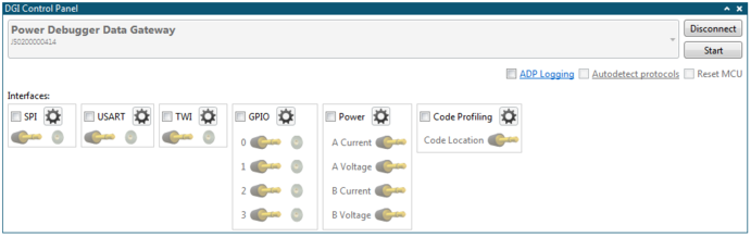
Data Gateway Interface (DGI) enables bidirectional communication over SPI, I2C, and USART, in addition to GPIO monitoring, power measurement, and code profiling.
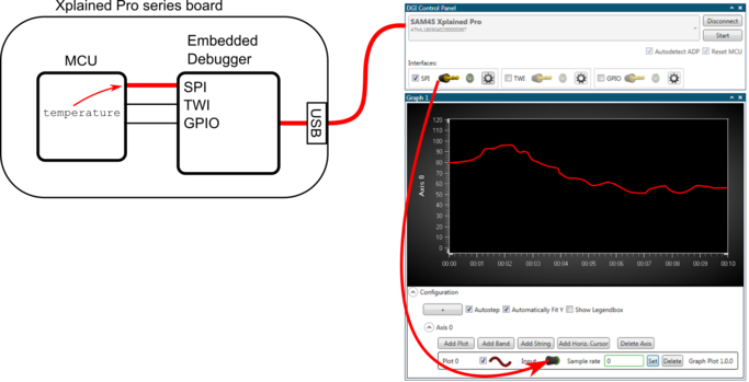
Graph
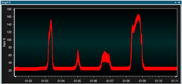
Graph can be used to plot data source values vs.
time.
- Cursors (time axis) to measure application timing (e.g., PWM frequency)
- Horizontal cursor (data values) to control an applicationʼs set point or threshold
- Band highlights time periods above customizable thresholds
- String markers can be used to add descriptive text to graphed events
Oscilloscope
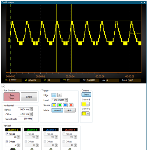
Oscilloscope
- Edge or threshold triggers on rising or falling edges
- Run-stop control for single shot or continuous triggering
- Cursors (time axis) to measure application timing (e.g., PWM frequency)
Power Debugging
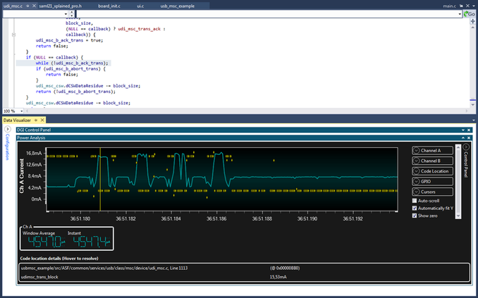
Power Debugging
- Correlation of code execution and power consumption
- Displays current and voltage measured using Power Debugger (Embedded debugger on some kits)
Custom Dashboard
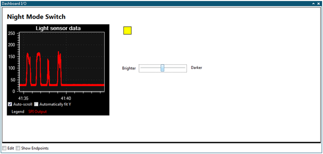
Custom Dashboard
- Build a custom user interface to visualize and control user application using: graph, segment display, binary signals, labels, buttons, linear gauge: Value within defined range. Pie Chart (e.g., for packets lost vs. transmitted in wireless application).
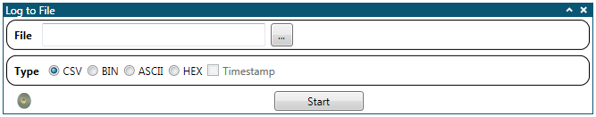
Utilities
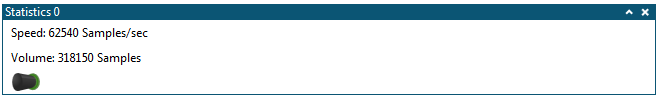
- Samplerate Counter to validate MCU frequencies (e.g., rate of transmitted ADC samples)
- File Logger module logs all incoming data to a file of selectable format